
Views: 0 Author: Site Editor Publish Time: 2026-10-21 Origin: Site


Unregulated water pressure is a silent, destructive force in fluid dynamics. Left unchecked, it causes catastrophic pipe bursts and massive underground leaks. It also inflicts severe damage on expensive downstream equipment. Implementing a robust control hydraulic valve water service directly solves this critical engineering issue.
These precision components act as the physical guardians of a piping network. They proactively stop damage before it occurs. Furthermore, they ensure a steady, predictable flow regardless of upstream volatility. In this technical guide, we will examine exactly how these mechanisms operate. We will break down the fluid physics behind their actuation and explore their deployment across municipal, industrial, and agricultural landscapes.
Before analyzing specific industry applications, we must establish a foundational understanding of pressure management mechanics. Professional fluid systems do not rely on guesswork. They depend on precision-engineered valves to dictate exactly how water behaves within a closed, pressurized network.
At its core, a hydraulic control valve is a specialized mechanical device designed to regulate fluid flow and pressure. Standard gate or ball valves require manual turning by an operator or rely on power-hungry electric motors. In contrast, a hydraulic valve utilizes the line pressure of the fluid itself as its primary power source. By redirecting a small volume of the upstream water through an external pilot circuit, the valve automatically opens, closes, or modulates its internal position. This self-powered nature makes it exceptionally reliable in remote geographical locations or during total electrical outages.
The operational engine driving most of these devices is the diaphragm valve architecture. This internal design features a flexible synthetic elastomer disc. It physically separates the upper control chamber from the main flow passage below.
The physics governing this mechanism are straightforward yet highly effective. When upstream water channels into the upper control chamber, it exerts downward hydrostatic force on the diaphragm. Because the surface area of the diaphragm is significantly larger than the valve seat, this downward force easily overcomes the upward kinetic energy of the flowing water. This pushes the rubber seal down to close the valve tightly. Conversely, when the pilot circuit vents water out of the control chamber, the line pressure pushes the diaphragm upward. Water then flows freely. This frictionless operation ensures a watertight seal while minimizing mechanical wear over decades of heavy use.
Global water infrastructure is currently undergoing a massive digital and mechanical transformation. Regulatory bodies worldwide are aggressively mandating the reduction of non-revenue water—treated supply that is lost to underground leaks before reaching the consumer. Consequently, passive pipe networks are evolving into active, data-driven smart grids. Advanced control valves now serve as the critical physical actuators in these modernized setups. They seamlessly integrate with SCADA systems to dynamically adjust pressure based on live neighborhood demand. This proactive approach significantly extends the lifespan of aging underground mains and conserves millions of gallons of fresh water annually.
Analyzing current industry trajectories reveals a massive shift in how global infrastructure handles fluid dynamics. Operators are rapidly transitioning from reactive pipe repairs to proactive pressure stabilization.
Municipal water grids face the relentless challenge of topography. Pumping treated water from a valley treatment plant up to a hillside reservoir requires immense hydrostatic pressure. However, when that same water flows back down into residential neighborhoods, gravity accelerates the flow. This generates extreme pressures that could easily rupture standard domestic plumbing fixtures. Municipalities install hydraulic valves at strategic elevation zones to step down this pressure safely. Implementing strict zone pressure control significantly reduces the stress on aging underground mains and virtually eliminates microscopic stress fractures.
In commercial real estate, vertical fluid dynamics present a unique engineering hurdle. Hydrostatic pressure increases by approximately 0.433 psi for every foot of vertical water column. In a 60-story skyscraper, water pumped to the roof creates catastrophic, pipe-shattering pressure at the ground floor if left unregulated. To manage this vertical column, engineers design pressure management stations on intermediate floors. These stations ensure that a ground-floor faucet experiences the exact same safe water pressure as a penthouse suite. Concurrently, they maintain the massive pressure reserves required for emergency fire sprinkler systems.
Industrial manufacturing facilities demand absolute precision in fluid control to maintain operational efficiency and workplace safety. In massive cooling towers, reverse osmosis desalination plants, and large-scale HVAC systems, flow rates must be strictly modulated. When a massive industrial pump cycles on, it sends a destructive hydraulic shockwave down the line. Hydraulic valves absorb this kinetic energy. They regulate makeup water flow and protect sensitive, expensive filtration membranes from immediate rupture.
Among the diverse configurations of hydraulic control devices, the pressure reducing valve remains the most universally applied component in modern fluid management.
A pressure reducing valve acts essentially as a mechanical shock absorber for a water network. Municipal supply lines frequently experience erratic pressure fluctuations due to changing neighborhood demand or sudden pump sequencing. This valve is finely calibrated to sense the downstream pressure. Regardless of how aggressively unstable the incoming upstream pressure becomes, the pilot system modulates the main diaphragm to deliver a steady, flat-line pressure to the downstream network. This continuous micro-adjustment prevents pipe bursts, protects sensitive commercial appliances, and mitigates the risk of catastrophic facility flooding.
Beyond simply lowering pressure, these valves play a critical role in fluid stabilization. Unregulated, high-velocity water causes water hammer—a destructive acoustic shockwave occurring when flow is suddenly halted. Additionally, extreme pressure drops across standard valves lead to cavitation. This violent phenomenon occurs when rapid pressure changes cause water to vaporize into microscopic bubbles. These bubbles instantly collapse, physically pitting and destroying solid metal pipes. Properly sized reducing valves maintain fluid velocities within safe engineering parameters. This eliminates cavitation, reduces structural pipe vibration, and significantly lowers acoustic noise.
Modern agriculture has evolved far beyond simple flooding techniques. Today, farming relies heavily on highly controlled, precision water delivery. In this sector, pressure management is directly tied to crop yield, resource conservation, and ultimate operational profitability.
Agricultural irrigation systems operate within razor-thin pressure tolerances. Drip irrigation tape delivers water directly to the plant root zone and typically requires a very low operating pressure of 10 to 15 psi. If mainline pressure reaches the drip lines, the thin plastic tape will instantly blow out and destroy the crop rows. Conversely, heavy-duty impact sprinklers require a strict minimum pressure threshold just to pop up and rotate correctly. An irrigation valve equipped with a pressure-reducing pilot ensures that water diverted from high-pressure mainlines is delivered to specific field zones at the exact pressure required by those specific emission devices.
Precision agriculture increasingly utilizes fertigation—the highly efficient process of injecting liquid fertilizers directly into the irrigation water stream. For fertigation to be chemically effective and environmentally safe, the water flow and pressure must remain absolutely constant. If pressure fluctuates during injection, fertilizer distribution becomes wildly uneven. This leads to chemical root burn in some areas and severe nutrient deficiency in others. A well-calibrated hydraulic valve maintains the steady flow necessary for uniform water and nutrient distribution.
While basic pressure reduction is the most common application, hydraulic control valves serve as versatile base platforms. By swapping the external pilot mechanisms, engineers configure them to perform highly specialized, complex tasks.
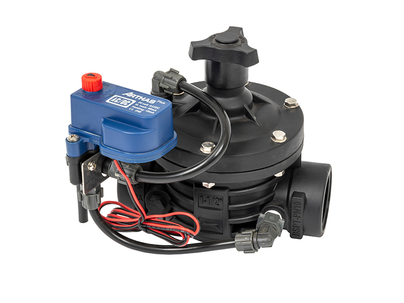
When an electric solenoid is integrated into the pilot circuit, the unit transforms into a solenoid control valve. This merges the rugged mechanical reliability of hydraulic power with the exact precision of digital automation. For example, a 2-inch T-type solenoid valve constructed from glass-filled nylon offers high flow capacity with minimal head loss. When equipped with a 24V AC or DC latching coil, it acts as an electronic trigger. It receives a low-voltage signal from a smart controller or SCADA system to open or close the hydraulic pilot. This technological bridge allows facility managers to remotely control water schedules from a smartphone and automate field operations based on live soil moisture sensors.
While reducing valves manage downstream conditions, pressure sustaining valves monitor and control upstream conditions. A sustaining valve remains tightly closed until the upstream pressure reaches a predetermined minimum setpoint. This ensures that critical primary supply lines are not completely drained by excessive secondary branch demands. Alternatively, pressure relief valves are installed on bypass lines. They remain closed under normal operating conditions but instantly pop open to discharge water if the line pressure spikes dangerously high. This acts as a critical, fast-acting safety mechanism against pump surges.
Selecting the correct valve for a pressure management system is an exact science. Specifying the wrong component based on assumptions leads to immediate system failure, premature wear, or erratic flow control. Project managers and engineers must evaluate several strict technical criteria before procurement.
A frequent and costly engineering error is sizing a hydraulic valve based purely on the existing pipe diameter. A valve that matches the pipe size is often massively oversized for the actual flow conditions. When a valve is oversized, it operates too close to its closed position. This causes valve hunting, where the diaphragm rapidly bounces open and closed, leading to severe pressure fluctuations and shredded elastomers. Conversely, an undersized valve restricts flow and causes excessive pressure loss.
Valves must be sized based on the system's actual flow rate. Engineers calculate this using Cv or Kv flow coefficients. Accurate calculation of both the maximum anticipated peak flow and the minimum continuous flow is mandatory to ensure the valve modulates smoothly across all demand scenarios.
The physical construction of the valve body must perfectly align with the operating environment and the chemical characteristics of the fluid. Below is a core engineering breakdown for material selection:
| Valve Material | Optimal Application | Key Engineering Benefit |
|---|---|---|
| Glass-Filled Nylon | Agriculture, Greenhouses, Fertigation | Highly resistant to corrosive chemical fertilizers; lightweight; zero rust risk. |
| Cast Iron | Municipal Water Grids, Fire Systems | High structural integrity; cost-effective for standard, non-corrosive water pressures. |
| Ductile Iron | High-Rise Buildings, Heavy Industrial | Superior tensile strength; withstands extreme pressure surges and water hammer. |
| Stainless Steel | Food & Beverage, Desalination Plants | Maximum corrosion resistance; handles aggressive water chemistry effortlessly. |
Even the highest-quality hydraulic valve will fail if installed or commissioned improperly. Adhering to strict, methodical installation protocols ensures the longevity of the control hydraulic valve water service.
Initial startup requires a careful, step-by-step procedure. Valves should never be subjected to full system pressure suddenly.
When a hydraulic control valve malfunctions, the root cause is rarely a complete mechanical failure of the main body. It is almost always a pilot obstruction or a calibration error.
A precisely engineered control hydraulic valve water service remains the structural backbone of any safe, highly efficient, and leak-free pressure management system. By brilliantly utilizing the physics of fluid dynamics, these devices provide unparalleled flow control without the constant need for vulnerable external electrical energy.
Whether the objective is mitigating pipe bursts in a sprawling municipal grid, automating precise fertigation on a commercial farm, or stabilizing cooling towers in a heavy industrial plant, selecting the correct valve type is a critical investment. Facility managers and agricultural engineers must rigorously evaluate their system's flow dynamics and specify high-grade components to ensure long-term infrastructural integrity. To explore a complete range of professional-grade pressure management solutions, including advanced glass-filled nylon solenoid valves and heavy-duty hydraulic controls, visit ARKA Irrigation and secure the exact specifications required for your next project.
While they look physically identical from the outside and utilize the same basic hydraulic principles, their pilot control mechanisms monitor entirely different zones. A pressure reducing valve is governed by a pilot that senses downstream pressure. It restricts flow to ensure the pressure after the valve never exceeds a safe limit. Conversely, a pressure sustaining valve monitors upstream pressure. It remains closed until the pressure before the valve reaches a specific minimum threshold, ensuring the primary pipeline maintains sufficient pressure before allowing water to flow further down the network.
Yes, entirely. The fundamental design of a hydraulic control valve relies exclusively on the kinetic energy and line pressure of the water flowing through the pipe. The water pressure is routed into a control chamber to hydraulically push the diaphragm open or closed. No external power source is required for basic operations like pressure reduction or surge relief. Electricity is only introduced when system designers add a solenoid pilot to the circuit for remote, electronic control.
Maintenance intervals depend heavily on the quality of the water passing through the system. In municipal applications processing clean, filtered potable water, a diaphragm valve can easily operate for five to ten years with minimal intervention. However, in agricultural settings exposed to raw well water, high sediment loads, and abrasive liquid fertilizers, maintenance must be more frequent. In these harsh environments, engineers recommend cleaning the pilot filters monthly and inspecting the main rubber diaphragm annually for signs of chemical degradation.
A loud, continuous humming, vibrating, or crackling noise is a primary indicator of cavitation. It often sounds like gravel flowing through the pipe. Cavitation occurs when the pressure differential across the valve is too extreme, causing the water to momentarily vaporize into micro-bubbles. As these bubbles pass into the higher-pressure recovery zone downstream, they violently collapse. This implosion generates intense localized shockwaves that create the noise and can literally erode the metal of the valve body over time. Resolving this requires installing two valves in series for staged pressure reduction.
Proper sizing requires calculating the flow coefficient based on the actual minimum and maximum flow rates of your system, rather than simply matching the existing pipe diameter. Engineers use specific formulas to determine the pressure drop across the valve at peak demand. If a valve is sized identically to a large pipe but only handles a small flow, it will barely open. This leads to erratic operation and accelerated wear. Always consult the manufacturer's flow charts to ensure the valve operates within its optimal mid-range capacity.
Valve hunting is characterized by the diaphragm rapidly bouncing between the open and closed positions, causing severe pressure spikes in the pipeline. This is almost always caused by an oversized valve attempting to regulate a very low flow rate. Because the valve is too large for the volume of water, a tiny movement of the diaphragm causes a massive change in pressure, confusing the pilot system. To fix this, engineers must either resize the main valve or install a smaller, secondary bypass valve specifically dedicated to handling low-flow periods.


