
Views: 0 Author: Site Editor Publish Time: 2026-10-27 Origin: Site


A newly commissioned piece of heavy machinery stalls on day one. Alternatively, a sprawling agricultural setup floods simply because a single component was mounted backward. Hydraulic systems are notoriously unforgiving. Misinterpreting a tiny symbol on a grease-smudged schematic often translates into ruptured seals, voided warranties, and exorbitant downtime. In this comprehensive guide, you will learn to decode a hydraulic control valve diagram with confidence. This fundamental knowledge bridges the gap between theoretical engineering and physical reality. It ensures safe installations and rapid, pinpoint troubleshooting.
For technicians, field engineers, and procurement managers, a fluid power drawing serves as far more than a basic illustration. It acts as the definitive blueprint dictating how pressurized fluid is directed, regulated, and maintained. Currently, the fluid power sector is experiencing a massive shift toward electro-hydraulic integration. Modern agricultural and industrial equipment frequently utilizes IoT-enabled smart valves and proportional controls. This technological leap makes system diagrams increasingly complex. As programmable logic controller signals and fluid power merge on the same page, relying on intuition instead of empirical schematic analysis is a guaranteed recipe for component failure.
Integrating a fluid power component demands absolute precision. A detailed diagram outlines the exact specifications required to select the correct hardware and orient it flawlessly. Connecting a high-pressure pump line to a low-pressure return port by mistake can instantly blow out internal spools. By thoroughly decoding the schematic before picking up a wrench, maintenance teams can verify flow paths and pressure thresholds. This targeted preparation effectively neutralizes the risk of catastrophic assembly errors.
When an actuator loses force or a machine completely stalls, diagnostic time directly drains profitability. Without a reliable drawing, troubleshooting devolves into a blind game of component swapping. Conversely, professionals who master schematics wield them like diagnostic treasure maps. They trace the exact journey of the fluid, bypassing working sectors to isolate the specific hardware that refuses to shift. Consequently, hours of manual testing are condensed into mere minutes of targeted visual inspection.
Hydraulic drawings rely on a universal visual lexicon governed primarily by ISO 1219 standards. Grasping this standardized anatomy is the foundational step in translating paper symbols into a functioning physical circuit.
The lines stretching across a schematic represent the physical steel pipes, flexible hoses, and internal manifold passages. Their specific formatting instantly communicates the nature of the fluid they transport. Working lines are depicted as solid lines, carrying the main pressurized oil from the pump to the cylinders, or routing it back to the tank. Pilot lines utilize dashed lines to represent low-pressure streams used exclusively to actuate other components. Furthermore, dotted lines signify drain lines. These safely channel internal leakage directly back to the reservoir to prevent dangerous pressure spikes inside the cast-iron housing.
Valves incorporate multiple connection points, universally referred to as ports. The diagram labels these with standardized letters, allowing installers to mate the correct physical hoses to the corresponding valve body threads. Specifically, P denotes the Pump or Pressure inlet receiving high-velocity fluid. The T port designates the Tank or Return line handling unpressurized exhaust. A and B represent the working ports connected directly to the actuators. Meanwhile, X and Y are reserved for external pilot pressure and pilot drain connections.
Directional control components are illustrated using a series of adjacent squares, often called envelopes. The total number of squares reveals how many distinct mechanical positions the spool can shift into. Inside these boxes, internal lines and arrows map out the fluid flow paths active during that specific state. For instance, a standard four-way, three-position configuration features four ports and three distinct operational positions. This is visually represented by three connected boxes.
A spool or poppet remains stationary until an external force compels it to move. The symbols attached to the outer edges of the envelope indicate the precise actuation method required to shift the mechanism from its resting state.
Manual actuators necessitate direct human intervention. You will typically see a simple vertical line denoting a hand lever, a mushroom shape for an emergency push-button, or a foot pedal icon. Mechanical controls, triggered by the physical movement of the machine itself, often appear as small circles representing rollers or plungers. In addition, a zigzag line attached to one end signifies a spring-return mechanism. This crucial detail dictates that the spool will automatically snap back to its default, unpowered position the moment the actuating force ceases.
In today's highly automated environments, manual shifting is becoming rare. An electromagnetic coil actuates a solenoid control valve, represented by a rectangular box with a diagonal line running through it. When voltage is applied, the resulting magnetic field physically pulls the internal armature. Alternatively, hydraulic pilot controls rely on fluid pressure to initiate movement. This is drawn as a dashed line terminating directly at the side of the envelope. It proves that fluid pressure, rather than electricity or muscle, provides the driving force.
Different industrial applications demand highly specialized architectures. Recognizing the unique symbols for varying pressure and directional regulators is paramount for accurate system analysis.
Unlike standard relief valves that dump excess fluid directly to the tank, a pressure reducing valve maintains a lower, strictly regulated pressure in one isolated branch of the circuit. Its symbol features a single square containing an arrow indicating the flow path, usually drawn in a normally open state. Crucially, a dashed pilot line extends from the downstream side of the valve back into the internal mechanism. This illustrates that the component constantly monitors downstream pressure, gradually closing off flow when the preset threshold is reached.
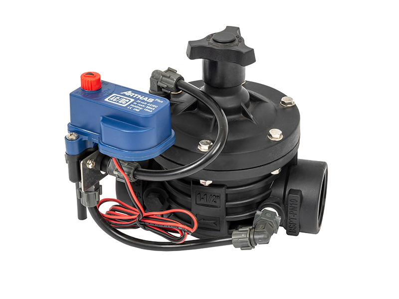
In agricultural sectors and municipal water management, fluid control relies heavily on specialized, debris-resistant components. An irrigation valve is frequently engineered as a diaphragm mechanism. On a drawing, the flexible membrane is represented by a curved line within the envelope, cleanly separating the upper control chamber from the main water passage below.
These units ingeniously use the line pressure of the fluid itself to operate. A dashed pilot line routes water into the upper chamber. When pressurized, it forces the rubber membrane downward, sealing the main flow path tight. Venting that pilot pressure allows the incoming line pressure to push the membrane back up, instantly opening the line. Grasping this specific logic is indispensable for agricultural engineers designing automated, multi-zone watering systems.
Transitioning from a two-dimensional paper schematic to a heavy, physical manifold requires methodical discipline. Skipping the verification phase frequently leads to blown seals, environmental spills, and ruined hardware. Below is a highly practical methodology to apply right before finalizing threaded connections.
Before mounting any hardware, locate the stamped data plate from the manufacturer. Cross-reference the part number and the etched ISO symbol directly with your diagram. You must verify that the number of ports, the available shifting positions, and the actuation methods align perfectly. If the drawing calls for a pilot-operated mechanism but you are holding a direct-acting lever unit, halting the installation is mandatory.
Never assume port locations based on visual symmetry or past experience. Use the diagram to map the specific routing of ports P, T, A, and B, then physically inspect the metal block for stamped lettering. Accidentally threading the high-pressure pump line into the Tank port can cause the cast-iron housing to fracture violently upon startup. The return port is rarely engineered to withstand maximum system spikes.
Hydraulic circuits must be engineered with inherent fail-safes. The drawing clearly indicates the unactuated, resting state of the system, visually represented by the box sitting adjacent to the spring symbol. Analyze the internal arrows of this specific resting box. If the arrow connects P to A or B, it is normally open. Fluid will surge to the cylinder the second the pump turns on. If P is blocked by a perpendicular line, it is normally closed. Verifying this default state prevents sudden, uncontrolled machine lurches that endanger nearby personnel.
Once a machine is commissioned, the schematic evolves from an assembly guide into a vital diagnostic instrument. When performance degrades, it provides a logical, step-by-step path for isolation.
| Schematic Indicator | Physical Symptom | Engineer's Diagnostic Action |
|---|---|---|
| Dashed pilot line to spool | Main valve fails to shift | Check pilot pressure gauge; inspect pilot orifice for debris blockage. |
| Diagonal line in solenoid box | Actuator unresponsive, no click sound | Test coil for 24V DC or AC voltage; check controller output signal integrity. |
| Dotted drain line from housing | Shaft seal blown, heavy oil leak | Verify drain line is routed directly to tank with zero backpressure. |
When a cylinder refuses to extend, mechanics face a classic dilemma. Is the coil burnt out, or is the hydraulic spool jammed? The diagram clarifies this relationship perfectly. By locating the solenoid symbol, you know exactly which electrical circuit to probe with your multimeter. If proper voltage is present at the plug but the cylinder remains static, the electrical signal is intact. This confirms the internal mechanical spool is likely seized by particulate contamination, requiring a physical teardown.
Internal leakage often manifests as a heavy load slowly drifting downward over time. Schematics help maintenance crews visualize exactly where high-pressure oil might bypass a worn internal seal and escape into the low-pressure return line. If a directional unit is resting in its blocked center position, yet the cylinder continues to creep, the diagram proves that fluid is bypassing the spool lands internally. This necessitates a full replacement rather than a time-consuming cylinder rebuild.
The ultimate objective of decoding a drawing is to ensure the physical hardware precisely matches the original engineering intent. While a schematic outlines functional logic, it completely omits physical dimensions, material tolerances, and flow capacities. Procurement teams must bridge this gap.
When sourcing a replacement, you must match the diagram logic with empirical real-world specifications. For setups requiring robust, high-volume fluid regulation, selecting an industrial-grade diaphragm valve is paramount. For example, modern agricultural irrigation systems frequently specify components like a 2-inch T-type solenoid valve. These units typically feature durable reinforced nylon bodies, handle operating pressures up to 10 bar, and utilize a 24V AC or latching DC coil for seamless integration with smart controllers.
Their lack of sliding internal spools makes them incredibly resistant to sand and grit. By aligning the precise pilot logic found on your schematic with reputable, heavy-duty manufacturers, you secure long-term, leak-free operation for your most critical systems.
Mastering the visual language of fluid power transforms a confusing web of lines into a clear, actionable blueprint. Reading these schematics accurately prevents costly installation blunders and drastically reduces the hours spent chasing ghost leaks and electrical faults. Always take the time to verify port connections and default resting states before engaging the main pump. By applying the systematic analysis techniques outlined in this guide, you will elevate your troubleshooting efficiency, safeguard your equipment, and significantly improve the operational lifespan of your next project. For engineers and procurement managers seeking reliable components that perfectly match complex schematics, exploring the high-performance catalog at Arka Irrigation ensures your physical build matches your theoretical design flawlessly.
You can determine the resting state by locating the spring symbol on the diagram. The box immediately adjacent to the spring represents the default, unpowered position. If the arrows inside this resting box connect the pressure port to the working ports, the pathway is normally open. In contrast, if the pressure port is blocked by a perpendicular line, it is normally closed, meaning fluid cannot pass until the mechanism is actively actuated.
This component is distinct from a standard relief valve. It is represented by a single square box containing an internal arrow indicating fluid flow, and its default state is normally open. Crucially, you will notice a dashed pilot line extending from the downstream side of the valve back into the box. This indicates the unit is sensing and regulating the pressure of the fluid exiting the component, rather than the pressure entering it.
In standard fluid power schematics, a dashed line represents a pilot line. When this line terminates at the side of an envelope, it indicates that the component is hydraulically or pneumatically piloted. Specifically, the physical shifting of the internal spool is achieved by applying fluid pressure against it, rather than relying on a manual hand lever, a mechanical roller, or an electrical solenoid.
Absolutely. The diagram is essential for isolating the root cause of an electrical-hydraulic failure. The schematic displays the exact correlation between the electrical actuation and the resulting fluid flow path. By referencing this, a technician can manually override the spool. If manual operation restores flow, the diagram confirms the hydraulic circuit is perfectly intact, proving the fault lies entirely within the electrical coil, the wiring harness, or the programmable logic controller signal.
Flow direction is indicated by the arrows drawn inside the position boxes. These arrows point from the supply ports toward the destination ports. It is vital to remember that these arrows only show the flow path for that specific actuated state, not a permanent, continuous flow. Always trace the solid line from the pump through the active box to determine where the fluid is traveling at any given moment.
A proportional unit is depicted similarly to a standard directional envelope, but it features two parallel lines drawn above and below the position boxes. Furthermore, the solenoid actuation symbol will have a diagonal arrow piercing through it. This specific arrow signifies that the spool can open gradually to throttle the flow rate precisely, rather than simply snapping completely open or completely closed.


