
Views: 0 Author: Site Editor Publish Time: 2026-10-27 Origin: Site


Pressure within fluid power networks is rarely static. A sudden unchecked spike can obliterate expensive downstream machinery in seconds. Fluid acts as the primary medium for power transmission in both complex industrial setups and agricultural fields. Liquids are largely incompressible. Any restriction in the flow path immediately translates into a volatile shift in pressure. Managing this volatility requires more than just sturdy pipes. It demands a dynamic infrastructure.
At the heart of this setup is the hydraulic control valve. This critical component functions as the central nervous system of fluid mechanics. A reliable valve setup automatically modulates downstream flow in response to unpredictable upstream pressure changes. This ensures baseline stability. The choice of component dictates the survival of the entire operation. This guide breaks down how these devices detect, interpret, and instantly react to pressure fluctuations on the field.
A control valve hydraulic system is an engineered network designed to direct and govern hydraulic fluid. The baseline physics rely heavily on fluid resistance and orifice size. Stand next to a high-pressure line, and you can feel the kinetic energy. As fluid is forced through a narrowed passage, resistance naturally increases. The internal mechanism manipulates this orifice size in real-time. This creates a calculated bottleneck that dictates exact pressure levels.
Engineers must look at Bernoulli’s principle to understand system stress. An increase in fluid speed occurs simultaneously with a decrease in static pressure. Throttling the flow path accelerates fluid velocity through that restriction. This causes a localized pressure drop.
It is crucial to distinguish between standard flow regulators and dedicated pressure regulators. Flow control devices maintain a constant flow rate regardless of pressure changes. Pressure-specific valves are explicitly designed to limit system force. They react to physical imbalances to protect the pipe network from catastrophic failure.
Valves detect pressure changes through raw physical force. In direct-acting models, fluid pressure pushes directly against a mechanical spring. Once the force exceeds the preset spring tension, the internal spool physically shifts. This direct pushback is incredibly reliable. However, it is limited to lower flow rates where forces remain manageable.
Pilot-operated architectures are the industry standard for high-volume modulation. These systems use a smaller internal pilot valve to control a massive main valve. Fluid routes to the pilot mechanism first. When a pressure shift occurs, the pilot opens and alters the hydraulic balance inside the main chamber. This two-stage process leverages the fluid's own power. It allows precise control over thousands of gallons with minimal effort.
Pressure regulation operates as a continuous feedback loop. If upstream suction pressure rises above the setpoint, the downstream valve modulates its internal geometry. This prevents dangerous spikes from reaching sensitive components.
Internal sensing ports achieve this instantaneous reaction. If downstream demand increases and pressure drops, the force acting on the sensing mechanism decreases. The opposing spring force immediately pushes the valve wider. This allows a larger volume of fluid to pass, restoring the target pressure. The physical adjustment happens seamlessly without human intervention.
A standard relief valve simply dumps excess fluid back into a reservoir during an emergency. In contrast, a pressure reducing valve actively steps down high incoming pressure. Operating typically in a normally open state, it provides a safe downstream environment. When pressure reaches the safety threshold, fluid fed back to the spool overcomes the adjustable spring tension. The spool partially closes the flow path. If pressure continues climbing, the valve seals completely.
The diaphragm valve excels in environments prone to fluid contamination. This design utilizes a flexible rubber sheet dividing the valve body into an upper control chamber and a lower flow chamber. The large surface area makes it highly responsive to minute pressure changes. Fluid introduced to the upper chamber flexes the diaphragm downward to restrict flow. This architecture eliminates sliding metal seals. It resists abrasive wear perfectly.
Electromechanical actuation takes over when millisecond response times are mandatory. A solenoid control valve uses an electromagnetic coil to move an internal plunger. This bridges the gap between digital control logic and physical fluid power.
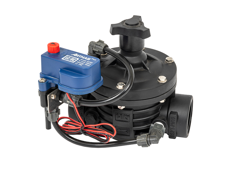
Take the Arka AS50SC-T 2-inch T-type solenoid valve as a prime example from the field. Operating seamlessly within a pressure range of 1.0 to 10.4 bar, it handles flow rates from 0.45 to 34.05 cubic meters per hour. The 24 VAC standard actuation ensures immediate response to controller signals. Integrating such precise parameters guarantees that water distribution remains exact, preventing both pipe burst risks and underwatering scenarios.
High-pressure circuits often exceed 3,000 PSI. These environments present severe physical challenges that tear standard components apart. Cavitation is the most destructive phenomenon engineers face. Fluid forced through a narrow orifice at extreme pressure skyrockets in velocity. Localized pressure drops below the vapor pressure. Vapor bubbles form instantly and collapse with explosive force downstream. Over time, these microscopic explosions pit solid metal surfaces.
Water hammer is another significant risk. A sudden valve closure creates a massive kinetic energy wave traveling back through the piping. This shockwave easily ruptures seals and causes structural fatigue.
Engineers mitigate these violent forces using heavy-duty construction. Machined ductile iron or forged steel replaces standard cast iron. Furthermore, these components employ customized internal geometries. Advanced throttle valves route fluid through labyrinth channels instead of a single harsh restriction. This steps the pressure down gradually. Engineered resistance neutralizes sudden pressure drops, effectively eliminating conditions that cause cavitation.
Water pressure is rarely uniform across expansive agricultural networks. Elevation changes, friction loss over long distances, and municipal pump cycling create volatile baseline pressures. To combat this, an irrigation valve is calibrated to smooth out variations. Utilizing a pilot-operated diaphragm system, it senses incoming surges and throttles flow automatically. Without this modulation, a sudden overnight pressure spike could easily burst mainlines or blow out delicate drip emitters.
Hydraulic systems dictate the precision of heavy machinery on the factory floor. Injection molding machines require exact pressure holding to function without destroying molds. Proportional servo valves are frequently deployed here. They continuously adjust spool positions based on electrical feedback. This allows a multi-ton press to descend with millimeter precision.
Warning signs are usually observable before total failure strikes. Erratic downstream pressure is the most glaring indicator. A machine actuator may stroke unpredictably. You might also notice system overheating as fluid bypassing a worn internal seal generates severe friction. A loud crackling noise emanating from the valve body is a classic auditory symptom of severe cavitation.
Failure to respond rarely stems from a fundamental design flaw. Teardowns reveal that maintenance oversights or environmental contamination are almost always the culprits. Particulate matter blocks microscopic pilot orifices, preventing the pressure signal from reaching the main spool. Mechanical fatigue sets in over millions of cycles. Springs lose tension, altering the pressure setpoint.
Diagnosing these issues requires a systematic approach. Field technicians should install pressure gauges upstream and downstream. Verify if the pressure differential matches system specifications. If readings remain erratic, manually override the valve to isolate mechanical binding from electrical failure. A thorough fluid analysis will reveal if metallic flakes or torn seals require immediate replacement.
The landscape of fluid power is rapidly shifting toward smart integration. Modern hydraulic setups are no longer purely mechanical. They are evolving into highly intelligent edge-computing nodes. We are witnessing a massive surge in smart valves equipped with integrated pressure transducers and IoT connectivity.
Instead of merely reacting to a pressure spike after it happens, these advanced systems analyze micro-fluctuations in real-time. Feeding this data into predictive maintenance algorithms allows facilities to identify pump degradation long before catastrophic failure occurs. This proactive approach drastically reduces unplanned downtime and optimizes energy consumption across large-scale fluid networks.
Selecting a valve based merely on existing pipe diameter is a critical engineering error. Valves must be sized according to their Flow Coefficient or Cv value. This represents the exact volume of fluid passing through the valve per minute at a specific pressure drop.
If a valve is oversized, the internal mechanism only needs to crack open slightly to meet flow demand. This forces the valve to operate unsteadily near its closed position. The resulting destructive cycle is known as hunting. The valve constantly opens and closes rapidly, causing severe pressure surges. Conversely, an undersized valve creates a permanent bottleneck.
Material composition must align strictly with fluid type and environmental demands. Actuation selection depends entirely on your required response times. Here is a quick reference guide for field selection:
| Valve Type | Best Application Scenario | Response Speed | Key Advantage |
|---|---|---|---|
| Direct-Acting Mechanical | Low flow, localized pressure relief | Moderate | Highly reliable, no external power needed |
| Pilot-Operated Diaphragm | Agricultural irrigation, untreated water | Gradual / Smooth | Resists debris, prevents water hammer |
| Solenoid Controlled | Automated setups, PLC integration | Milliseconds | Digital precision, remote operation |
By meticulously matching the Cv value, material, and actuation method to your operational demands, you guarantee a robust system.
Understanding the internal mechanics of your hydraulic infrastructure is non-negotiable for maintaining a safe fluid power system. These components are not passive pieces of pipe. They are dynamic instruments that constantly interpret the laws of fluid physics.
The correct valve setup anticipates system needs and shields expensive machinery from catastrophic shock. Facility managers should proactively audit their current hydraulic circuits for pressure inefficiencies.
Are you experiencing erratic pressure drops or looking to upgrade your agricultural irrigation network? Selecting precisely calibrated components eliminates costly risks. Explore the full range of high-performance solutions at Arka Irrigation today to find the exact configuration your system demands.
The primary difference lies in their fundamental purpose. A pressure relief valve is a safety device protecting the system from over-pressurization. It remains normally closed, opening only to divert excess fluid. In contrast, a pressure reducing valve is an active regulation device. It actively throttles flow to maintain a constant, lower downstream pressure.
Solenoid valves are engineered for exceptionally rapid response times. When a sensor detects an anomaly, the electrical signal energizes the magnetic coil. In direct-acting DC systems, this occurs in approximately 30 to 50 milliseconds. AC solenoids can respond within 15 to 20 milliseconds.
This architecture is the industry standard for agriculture due to its tolerance for contaminated fluids. A diaphragm valve uses a flexible rubber sheet to seal against the seat. The pilot mechanism is physically isolated from the main fluid chamber. Dirt and mineral deposits found in raw water cannot jam the internal components.
Installing a valve with a flow capacity that is too large introduces severe instability. The valve operates extremely close to its seat. Microscopic movements cause massive changes in flow. The system overcorrects, forcing the valve to rapidly open and close. This destructive cycle causes intense vibrations and eventual mechanical destruction.
An automatic flow control valve cannot serve as a dedicated pressure regulator. Its primary function is to maintain a constant flow rate regardless of pressure fluctuations. It does not establish a hard boundary for maximum system pressure. Dedicated pressure control valves must be integrated for strict protection.
Adjusting the pressure typically involves turning the set screw or adjustment knob located on the pilot valve or main spring housing. Turning it clockwise increases spring tension, which raises the pressure setpoint. Turning it counterclockwise decreases tension, lowering the setpoint. Field engineers always recommend making these adjustments gradually while monitoring a calibrated pressure gauge to avoid sudden downstream shocks.
Valve sticking is almost universally caused by fluid contamination or thermal expansion. Microscopic metal shavings or degraded seal particles can wedge between the spool and the valve body. Additionally, extreme heat can cause internal metal components to expand at different rates, eliminating the microscopic clearances required for smooth operation. Routine fluid flushing and maintaining proper operating temperatures are the best preventative measures.


