
Views: 0 Author: Site Editor Publish Time: 2026-10-15 Origin: Site


Are clogged emitters ruining your crops? Setting up a complex agricultural or residential watering network only to face a burned-out pump or blocked drip lines is a massive, yet entirely preventable, headache.
The root of this problem usually comes down to one critical hydraulic design choice. Should the protective screen go before the pump on the suction side, or after the pump on the discharge side? Get this layout wrong, and you will destroy expensive equipment while crippling your flow rates. You must choose the exact right location to ensure system longevity.
Getting this architecture right is the difference between a setup that runs flawlessly for decades and one that suffers catastrophic mechanical failure in a single week. Both sides of the pump require protection. However, the specific type of barrier used on each side is entirely different. Let us break down the strict engineering rules of suction versus discharge setups, ensuring your equipment operates exactly as intended.
Understanding the fundamental mechanics of water movement is the absolute first step in designing a reliable layout. Every single component in your plumbing architecture serves a highly specific mechanical purpose. Confusing these purposes inevitably leads to rapid equipment degradation.
Filtration in any water transfer application serves a dual purpose. First, the water pump itself requires a physical shield against large, hard objects. If items like pebbles, thick twigs, or aquatic shells are sucked into the casing, they will instantly shatter a plastic impeller or severely chip a cast-iron one. Therefore, the intake needs a robust barrier against macro-debris.
Furthermore, the actual emitters require stringent protection from microscopic particulates. A standard drip tape features a tiny, labyrinth-like flow path. This path can easily become permanently blocked by sand, silt, or organic matter like algae. Ultimately, the heavy-duty hardware required to stop a river rock is vastly different from the precision mesh required to stop a grain of sand.
The origin of your water dictates the complexity of your entire plumbing architecture. Clean municipal water typically arrives pre-treated and pressurized. In these specific scenarios, you generally only need a basic screen to catch minor pipe rust or municipal scale.
In contrast, drawing water from untreated sources such as lakes, muddy ponds, or shallow agricultural canals introduces heavy biological and mineral loads. These raw sources demand highly robust, multi-stage separation tactics to actively remove suspended solids before they can reach sensitive downstream valves. Evaluating the specific turbidity and organic content of your water source is a mandatory prerequisite for proper hardware selection.
The suction side consists of the piping that connects the raw water source directly to the inlet port. Modifying this side of the system requires strict adherence to the laws of fluid dynamics.
Centrifugal pumps are engineered specifically to push water, not pull it. When a motor operates, the spinning impeller creates a partial vacuum at its eye. Standard atmospheric pressure then pushes the source water up into that vacuum. Because ambient atmospheric pressure is relatively weak, the pump has a very limited ability to overcome friction or resistance on the intake side.
Consequently, any object placed in the suction line creates drag. If you place a restrictive barrier here, the ambient atmospheric pressure simply cannot push the heavy fluid through the barrier fast enough to keep the volute fully fed.
You must use a coarse strainer on the suction side. Acceptable and safe components include heavy-duty metal screens, intake strainers, or brass foot valves. The sole objective of this coarse guard is to stop debris large enough to physically jam the impeller, while allowing fluid to flow freely.
As a general engineering guideline, the total open surface area of a suction screen should be at least three to four times the cross-sectional area of the suction pipe. This intentionally oversized surface area ensures that even if a plastic bag or a clump of leaves clings to the outside of the screen, the underlying water flow remains largely unrestricted.
Installing a fine mesh or stacked disc unit before the pump is a critical, often fatal, design error. A barrier designed to catch fine sand or algae creates immense friction. As this fine screen inevitably catches dirt, the resistance multiplies exponentially. The motor will desperately attempt to draw water, but the clogged fine mesh acts exactly like a closed valve. This starves the internal seals of the fluid required for cooling, leading directly to catastrophic burnout.
When well-meaning users mistakenly place fine screens on the intake side, the most common and destructive result is cavitation. This is a violent physical phenomenon that can ruin a brand-new setup in a matter of hours.
Cavitation occurs when a system cannot draw enough fluid due to a restricted suction line. As the motor continues to spin against this severe restriction, the internal pressure inside the volute drops significantly. When the pressure falls below the vapor pressure of the fluid, the water literally begins to boil at normal ambient temperatures.
This localized boiling creates thousands of microscopic vapor bubbles. As these bubbles pass through the spinning impeller and enter the higher-pressure discharge zone, they violently collapse or implode. These rapid implosions generate localized shockwaves that pit, erode, and tear apart the metal or plastic surfaces of the impeller. Eventually, this destroys the equipment from the inside out, leaving the metal looking as though it has been chewed by termites.
To prevent this destruction, hydraulic engineers calculate the Net Positive Suction Head. Every pump has a specific requirement dictated by the manufacturer to operate smoothly. Conversely, the plumbing system you build provides the available head pressure.
For any motor to survive its operational lifespan, the available pressure must always remain greater than the required pressure. Placing a restrictive, fine mesh on the suction side artificially plummets the available head. As organic debris collects, the available pressure drops further until it falls below the minimum requirement, triggering immediate and loud cavitation.
The discharge side represents the pressurized piping that exits the volute and leads directly to your fields or landscape. This is the only mathematically and mechanically sound location for precision, fine filtration.
Unlike the suction side, which relies on relatively weak atmospheric pressure, the discharge side is powered by brute mechanical force. A standard agricultural or residential setup can easily generate 40 to 80 PSI on the discharge manifold.
Because centrifugal systems are highly efficient at pushing fluid through resistance, placing your primary fine mesh here is perfectly safe. The high pressure easily forces fluid through microscopic screens to catch sand, silt, and algae without starving the motor of its essential flow.
The discharge unit acts as the ultimate, uncompromising bodyguard for the rest of the network. Micro-irrigation setups, particularly pressure-compensating drip tapes, have incredibly tight internal tolerances. A single grain of coarse silica sand can permanently disable a dripper. By placing the fine mesh immediately after the pump, you guarantee that only clean, particulate-free fluid enters the manifold and delicate solenoid valve assemblies.
| Feature | Suction Side Placement | Discharge Side Placement |
|---|---|---|
| Primary Function | Protects the pump impeller from large, hard debris. | Protects downstream emitters and valves from fine particulates. |
| Filter Type Used | Coarse strainers, large perforated screens, foot valves. | Fine wire mesh, stacked disc, or automated backflush systems. |
| Operating Pressure | Negative pressure pulled by atmospheric vacuum. | High positive pressure driven by mechanical force. |
| Risk of Blockage | High risk of pump cavitation and motor burnout if clogged. | Safe. Causes a manageable pressure drop across the system. |
Selecting the correct separation technology is just as important as choosing the correct placement side. Different materials and internal designs excel at capturing vastly different types of debris.
For the suction side, your focus must remain entirely on maximum flow and minimal restriction. Acceptable hardware includes large intake screens, which are perforated metal or heavy-duty plastic cylinders placed directly into the source. Foot valves are also standard. They combine a coarse screen with a check valve, keeping the lines primed while blocking large rocks.
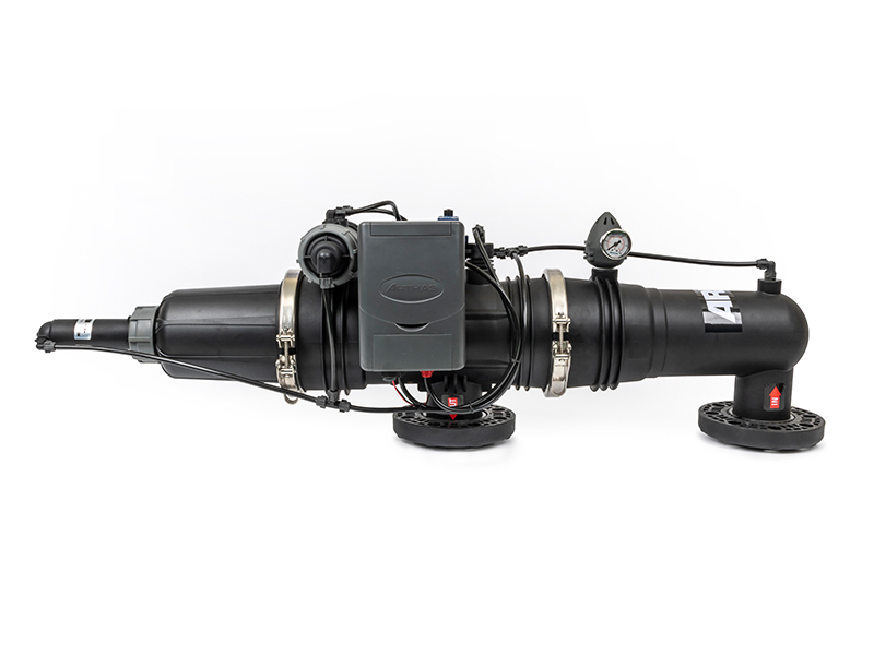
The discharge side requires precision technology to safeguard emitters. For high-volume or commercial agricultural applications, upgrading to an automated irrigation filter system is the smartest investment a grower can make.
Let us look at actual field specifications. A professional-grade 3-inch auto backflush self-cleaning unit utilizing a stainless steel wire mesh screen handles heavy sediment loads effortlessly. These advanced designs trap fine particles down to 120 or 200 mesh. When the internal differential pressure reaches a specific limit, the automatic backflush mechanism activates. It purges the accumulated dirt in seconds without interrupting the main water flow to your crops. This specific 3-inch high-capacity design ensures massive flow rates while maintaining an incredibly low pressure drop, saving you countless manual labor hours.
As water scarcity becomes a more pressing global issue and agricultural labor costs continue to rise, the sector is experiencing a massive shift in fluid management strategies. Recent engineering trends highlight a rapid transition away from manual, labor-intensive maintenance toward smart, automated infrastructure.
Specifically, modern farm operators and commercial landscapers are prioritizing low-pressure-drop technologies and self-cleaning mechanisms. The primary goal is maximizing energy efficiency. A unit that cleans itself before the pressure drops too low saves the motor from working overtime, thereby drastically reducing electricity costs. Furthermore, the integration of IoT sensors allows operators to monitor differential pressure remotely via smartphones. This proactive approach to system health ensures that modern irrigation water filters operate at peak efficiency at all times. This technological shift reflects a broader industry commitment to sustainable, precision agriculture where every drop of water and watt of energy is optimized.
Extracting raw fluid from natural, untreated bodies of water presents unique engineering challenges. The quality can fluctuate wildly based on seasonal rainfall, temperature spikes, and agricultural runoff.
When pulling from ponds or canals, the physical placement of the suction pipe in the water column is critical. You should never let the intake screen rest directly on the bottom of the lake. If you do, the motor will vacuum up dense mud, sludge, and decaying leaves. Conversely, placing the intake too close to the surface will draw in floating algae mats and create air vortexes that introduce damaging air bubbles into the volute.
The most effective strategy is the suspended intake method. Secure the intake pipe to a floating buoy or pontoon, and suspend the coarse screen roughly 18 to 24 inches below the surface. This taps into the absolute cleanest cross-section of the water column.
For agricultural setups dealing with highly turbid sources, a single barrier is rarely sufficient. A proper multi-stage setup distributes the debris load across several components. First, a coarse intake screen suspended in the lake stops frogs, sticks, and large algae mats. Next, the motor pressurizes the system. Immediately after the volute, a centrifugal sand separator removes heavy, abrasive sand particles using rotational force. Finally, a fine automated wire mesh catches the remaining microscopic silt just before the fluid reaches the delicate drip tape.
Implementing the correct layout is critical to achieving optimal flow rates and protecting your hardware. A poorly installed network can lead to immediate mechanical failure or chronic underperformance. Following a standardized, engineering-backed installation sequence ensures that your equipment operates within its designed hydraulic parameters.
Securing the Foot Valve and Coarse Screen
The first line of defense is located exactly where the fluid enters your network. For surface sources, install a coarse intake screen or a foot valve at the end of your suction line. Ensure all PVC or poly pipe joints are completely airtight. Even a microscopic pinhole leak will allow air in, causing the motor to instantly lose prime.
Plumbing the Water Pump
When connecting the piping, precision is essential. The suction pipe should ideally be one size larger than the intake port to reduce friction loss. Avoid using 90-degree elbows directly at the inlet, as this causes turbulent flow. Incorporate isolation shut-off valves and PVC unions on both the suction and discharge sides. Instead of wrestling with a hacksaw in the mud later, this structural choice allows you to easily isolate and remove the motor for winterization or repair.
Mounting the Primary Unit on the Discharge Manifold
The fine precision unit belongs strictly on the discharge side. When mounting this hardware, carefully observe the directional flow arrows stamped on the housing. The arrow must point away from the pump and toward the field. Installing it backward forces fluid against the internal structural supports of the screen cartridge, leading to immediate structural collapse under high pressure. Ensure the housing is mounted securely to a backboard or supported by pipe stands to prevent vibration-induced stress on the plumbing joints.
Adding Pressure Gauges for System Monitoring
A setup is completely blind without diagnostic tools. Install two liquid-filled pressure gauges. Place one immediately upstream before the housing and one immediately downstream after it. These gauges are vital instruments that measure the differential pressure across the internal element. Without them, operators are forced to guess when the screen is dirty, which often leads to dangerous neglect.
Even the most meticulously designed agricultural or residential networks require consistent maintenance. Neglecting your hardware leads to exponential pressure drops, reduced emitter uniformity, and ultimately, severe crop stress.
Instead of relying solely on a calendar, rely on empirical data provided by your instrumentation. The most accurate method to determine when your equipment requires maintenance is by monitoring the differential pressure. When the mesh is completely clean, the pressure drop across the unit is minimal, usually around 1 to 3 PSI. As dirt accumulates, fluid struggles to pass through the restricted microscopic pores. This causes the pressure before the housing to rise and the pressure after it to drop.
As a standard industry rule, when the mathematical difference reaches a 7 to 10 PSI drop, it is time to clean the element. Allowing the differential pressure to exceed 15 PSI places severe mechanical stress on the wire mesh. At this stage, a sudden rush of abrasive silica sand can tear the screen, allowing debris to flood your delicate drip lines.
For large-scale agricultural operations or commercial landscapes dealing with exceptionally dirty sources, manual scrubbing quickly becomes a massive labor burden. Upgrading to an automated solution is a highly recommended strategy to ensure continuous protection.
Integrating a high-quality, self-cleaning irrigation filter system into your discharge line completely eliminates the risk of human error. These automated units monitor the differential pressure internally. When the pressure drop reaches the predetermined threshold, the system automatically reverses the flow. It flushes the accumulated debris out of a discharge valve while the motor continues to run. This transition from manual labor to automated maintenance significantly reduces operational downtime.
Proper hardware placement is the ultimate safeguard for your water network. Always place coarse strainers on the suction side to prevent dangerous cavitation and motor overheating. Conversely, you must install fine precision mesh on the pressurized discharge side to protect your delicate drip emitters and sprinkler heads from microscopic clogging.
An efficiently designed layout saves thousands of dollars in ruined hardware and wasted labor hours. By regularly checking your dual pressure gauges and utilizing the suspended intake method for surface water, you guarantee optimal flow rates. Evaluate your current plumbing architecture today. If you are tired of manual scrubbing and clogged lines, explore the high-performance solutions at Arka to find the exact automated backflush technology your system needs for unmatched, long-term reliability.
No. Placing a 120-mesh screen on the suction side is a critical design flaw. A 120-mesh screen has microscopic openings designed to catch fine sand and silt. When placed before the intake, these small pores quickly become obstructed. Because centrifugal motors are designed to push fluid rather than pull it, this obstruction creates a severe vacuum. The restricted flow lowers the internal pressure so drastically that the fluid begins to boil at ambient temperatures. This destructive phenomenon is known as cavitation. Fine precision mesh must always be placed on the pressurized discharge side.
Yes. While municipal water is treated and safe for human consumption, it travels through miles of underground infrastructure before reaching your property. Along the way, it picks up pipe scale, rust flakes, calcium deposits, and mineral build-up. Furthermore, municipal system repairs often introduce sudden flushes of sediment into the water mains. Micro-irrigation setups have extremely small orifices that can be permanently clogged by a single flake of rust. Installing a discharge-side unit acts as an inexpensive insurance policy.
The primary difference lies in their structural design and their intended mechanical function. A suction strainer is a robust, coarse mesh device installed before the intake. Its sole purpose is to stop massive debris like rocks, twigs, or aquatic life from entering the housing and physically shattering the spinning impeller. It is not designed to clean the fluid. In contrast, a discharge unit is a highly refined component installed after the volute. It utilizes fine wire mesh or synthetic discs to capture microscopic particles, preventing them from clogging sensitive downstream emitters.
The most empirical and reliable way to know when your equipment requires cleaning is by reading the liquid-filled pressure gauges installed on either side of the housing. When the mesh is clean, both gauges will display roughly the same pressure. As debris builds up inside, the upstream pressure will increase while the downstream pressure decreases. When the mathematical difference between these two gauges reaches between 7 and 10 PSI, the element is dirty and requires immediate manual cleaning or backflushing. Relying on visual guesses often leads to dangerous neglect.
Drip tape and micro-sprinklers require highly filtered water due to their tiny flow paths. The industry standard for protecting drip irrigation is typically between 120 mesh and 200 mesh. A 120-mesh screen will filter out particles larger than 125 microns, which is sufficient to stop fine sand and most organic particulates that cause permanent emitter blockages. Always consult your specific drip tape manufacturer's specifications to ensure you select the exact required mesh size.
Yes. If the coarse intake screen becomes completely blinded by plastic bags, dense algae mats, or thick mud, the motor will be starved of fluid. As it struggles to pull against the severe restriction, it can draw air in through microscopic imperfections in the PVC joints or valve seals. Once enough air accumulates inside the volute, the motor loses its prime and stops moving fluid entirely, which will quickly lead to overheating and seal failure if not shut down immediately.


