
Views: 0 Author: Site Editor Publish Time: 2026-10-15 Origin: Site


Clogged emitters bleed profit. Every single day, commercial farms lose thousands of dollars in wasted labor and ruined crop yields simply because poor water filtration allows debris to bypass the pump house. When unfiltered particulate matter hits the field, it disrupts the precise hydraulic balance of your irrigation network, causing uneven water distribution and severe plant stress. In these high-stakes agricultural environments, the treatment equipment guarding your main lines is your first and most critical line of defense.
Sizing this infrastructure for a massive commercial project is never a guessing game. As any seasoned water engineer will tell you, it demands a rigorous understanding of fluid dynamics, raw water particulate loads, and the exact physical tolerances of your field emitters. This comprehensive engineering guide breaks down the exact methodology required to spec your filtration manifold. By mastering the balance between flow rates, dirt loads, and automated cleaning cycles, you can secure your long-term agricultural investments against catastrophic hydraulic failure.
Modern commercial agriculture is undergoing a massive hydraulic transition. Driven by escalating groundwater depletion and erratic climate patterns, farm operators are increasingly forced to abandon pristine deep wells. Instead, they are pivoting toward marginal supplies, including recycled agricultural effluent, open canals, and shallow retention ponds. This industry-wide shift introduces a severe complication: these open sources carry dramatically higher levels of Total Suspended Solids.
Consequently, the engineering standards for agricultural water treatment have evolved. Ten years ago, a basic screen might have sufficed for a clean aquifer. Today, handling aggressive biological loads requires robust, high-capacity depth filtration matrices. Farm managers are quickly realizing that investing in advanced, self-cleaning infrastructure is no longer an optional upgrade but a baseline requirement for survival in modern precision farming.
Raw environmental water is rarely clean. It carries a complex burden of suspended silt, biological slime, and abrasive inorganic particles that threaten highly precise modern drip networks. Acting as the primary physical barrier, a properly engineered disc filter isolates and extracts these contaminants before they ever reach your delicate field infrastructure.
The core mechanism relies on tightly compressed stacks of color-coded synthetic rings housed inside a high-pressure polymer shell. As raw water is forced from the outside of the compressed stack toward the hollow center spine, the intersecting diagonal grooves on each ring create a dense, three-dimensional trapping matrix. Engineers refer to this highly efficient process as depth filtration.
Traditional screen filters operate on a fundamentally different principle. Relying on a single layer of stainless steel mesh, screens provide only two-dimensional surface filtration. While adequate for catching rigid well sand, screens fail catastrophically against soft biological matter. When an algae bloom hits a metal screen, the organic matter flattens out and instantly blinds the pores, triggering a massive pressure spike across the manifold. Depth filtration bypasses this fatal flaw. The grooved layers capture soft, deformable particles deep within their intersecting channels, allowing clean water to pass through without instantly choking the system. Compared to massive sand media tanks, these modern modular systems require a fraction of the installation footprint, consume far less backwash water, and entirely eliminate the risk of abrasive silica escaping into your main lines.
The physical footprint, header configuration, and total capital cost of your pump station are directly dictated by the quality of your raw water. A frequent and costly pitfall among novice project managers is attempting to size a manifold based purely on the pump flow rate. In reality, the particulate load must be rigorously evaluated to ensure the station possesses enough physical surface area to operate efficiently without entering a continuous cleaning loop.
Treating high-load sources requires engineers to specify much larger, more resilient systems to handle the sheer volume of dirt entering the intake header.
Different environments inject vastly different contaminant profiles into your hydraulic network.
Accurate engineering starts with a baseline water quality test to determine the Total Suspended Solids, usually measured in parts per million or milligrams per liter. The engineering rule of thumb is absolute: the poorer the raw water quality, the larger the physical filter area required to sustain your target field flow.
| Water Source Type | Expected Dirt Load Range | Primary Contaminant Profile | Filtration Area Requirement |
|---|---|---|---|
| Deep Aquifer | 0 to 50 parts per million | Silica sand, rust, mineral scale | Standard baseline sizing |
| Shallow Well | 50 to 100 parts per million | Heavy silt, fine suspended sand | Moderate up-sizing required |
| Retention Pond | 100 to 250 parts per million | Algae blooms, soft organic matter | High surface area required |
| River or Open Canal | Over 250 parts per million | Heavy seasonal mud, debris, moss | Maximum surface area and pre-treatment |
Hydraulic sizing errors almost always occur when designers base the manifold dimensions on the theoretical maximum output of the main pump, rather than the actual fluid dynamics required by the crop zones.
Your infrastructure must comfortably process the maximum volumetric demand of your largest single irrigation block. To calculate this metric out in the field, count the total number of emitters in that specific zone and multiply it by the output rating of a single emitter.
Imagine a high-density orchard block covering 20 acres, equipped with 10,000 emitters per acre. If each dripper is rated for exactly 0.5 gallons per hour, the total zone demand hits 100,000 gallons per hour. This translates to roughly 1,666 gallons per minute. The manifold you specify must handle this peak velocity without causing severe friction loss or exceeding the manufacturer's recommended flow limits for the header pipes.
A critical metric that frequently blindsides inexperienced designers is the secondary backflush flow requirement. An automatic disc filter cleans its internal matrix by reversing the flow of highly pressurized, clean water backward through the synthetic rings. This self-cleaning process consumes fluid that would otherwise be hydrating your crops.
If your field requires 1,666 gallons per minute to maintain optimal operating pressure, and a single 3-inch or 4-inch pod in your manifold requires 150 gallons per minute to execute a violent backwash spin, your actual required output at the pump station is 1,816 gallons per minute. Ignoring this extra volume guarantees a severe pressure drop across your drip lines every time the controller triggers a cleaning cycle, leading to dry spots and stressed plants.
Selecting the exact micron rating is a strategic balancing act. The engineering objective is to capture particles large enough to plug your specific emitters while allowing microscopic, harmless silt to flow freely through the lines. Striking this balance drastically reduces unnecessary backwash cycles and saves immense amounts of water.
The golden rule of agricultural hydraulics dictates filtering out any particle that is one-tenth the size of the emitter's narrowest internal pathway.
Many farm operators mistakenly believe that finer protection is always superior. Hydraulically speaking, this is false. Installing a 100-micron matrix when a 200-micron rating is sufficient forces the system to trap microscopic mud that poses zero threat to the crops. This over-filtration chokes the matrix rapidly, spiking the differential pressure and forcing the manifold into an endless backwash loop. Ultimately, this burns through electricity, wastes treated water, and accelerates wear on the backflush valves.
For operations managers controlling the capital expenditure budget, selecting the correct level of automation dictates the long-term labor overhead and reliability of the entire farm.
A Y type disc filter is a manually serviced unit housed in an industrial polymer body. Cleaning it requires a field technician to shut down the main isolation valve, unthread the housing, extract the internal spine, loosen the compression cylinder, and manually blast the rings clean with a pressure washer.
While exceptionally effective at capturing dirt, manual housings are labor-intensive. Engineers typically deploy them in small greenhouse zones, low-flow nursery setups, or as secondary insurance checkpoints installed directly at the remote field valves.
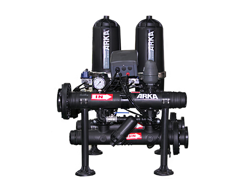
For massive commercial acreage, an automated self-cleaning station is an absolute operational necessity. Modern engineered solutions, such as the ARKA F202 T-Type Auto Backflushing systems, utilize an intelligent pressure differential switch. As algae and mud build up on the outer edges of the matrix, the fluid pressure on the discharge header begins to drop. Once the controller detects a pressure difference of roughly 7 to 10 psi between the inlet and outlet, it fires a highly synchronized backwash sequence.
The return on investment becomes obvious within the first season. Automation completely eliminates the need for daily maintenance crews. More importantly, modular T-Type systems clean one pod at a time while the remaining pods continue supplying clean water to the field, ensuring zero interruption to the crop hydration schedule.
Mastering pressure dynamics is the final step in successfully integrating a treatment station into a high-capacity pumping network.
Inserting any physical barrier into a pipeline introduces friction, resulting in a measurable pressure drop known as Delta P. A properly engineered, freshly cleaned manifold should exhibit a minimal friction loss of roughly 2 to 4 psi. This low baseline proves that fluid is passing through the grooved matrix without severe restriction.
As the dirt load accumulates, those microscopic pathways narrow. The main pump must work significantly harder to force the same volume of water through the restricted rings, causing the differential pressure to climb. If your newly installed manifold shows a 10 psi pressure drop immediately after a thorough backwash, the system lacks the physical surface area required for your flow rate and is severely undersized.
Relying on a single, gigantic steel housing for a commercial farm is a massive operational risk. Instead, water engineers specify modular manifold configurations. A modular setup connects multiple independent pods, such as a 3-unit or 4-unit array, in parallel along common intake and discharge header pipes.
This design relies on the N plus 1 redundancy rule. If your hydraulic math shows that three pods are required to handle the peak flow, you must install a four-pod manifold. This critical buffer ensures that when one unit isolates itself to perform a high-pressure backwash, the remaining units can easily process the full field demand without starving the drippers of operating pressure.
Even veteran agricultural designers occasionally make critical errors during the procurement phase. Review these common field failures to protect your project:
Downsizing the manifold to artificially shrink the initial equipment cost is a punishing mistake. A smaller setup might handle your baseline flow on a spreadsheet, but it leaves zero buffer for when water quality inevitably crashes during a July algae bloom. An undersized matrix will choke instantly, triggering non-stop flushing cycles that waste massive amounts of water and burn out pump motors.
Automated stations require aggressive hydraulic pressure to clean themselves effectively. During a flush cycle, a hydraulic piston releases the tension on the stack, allowing the individual rings to separate so trapped dirt can be violently spun out. If your header pressure drops below the manufacturer's strict minimum requirement, usually around 35 to 40 psi, the rings will fail to separate. The flush water will simply bypass the trapped algae, leaving the pod permanently clogged.
While synthetic depth matrices are unmatched at capturing soft organic slime, they are not built to absorb the impact of heavy, abrasive river gravel. If your intake pulls from a fast-moving, sandy canal, you must install a centrifugal sand separator upstream. This pre-treatment uses centrifugal force to spin heavy rocks out of the water, preventing the downstream synthetic rings from being chewed apart.
Commercial farms expand constantly. A block requiring 500 gallons per minute today might demand 800 in three years. Sizing your header pipes exactly to your current flow leaves you trapped. Smart hydraulic design involves installing a manifold equipped with blind flanges. When the farm grows, your maintenance team simply unbolts the cap and adds an extra T-Type pod, avoiding a massive and expensive plumbing rebuild.
Selecting the right equipment manufacturer is just as critical as your flow calculations. Large-scale agriculture destroys cheap plastics. You need industrial-grade polymers, corrosion-proof manifolds, and heavy-duty backwash valves built to survive aggressive liquid fertilizers, intense UV exposure, and thousands of actuation cycles.
When evaluating suppliers, demand modular systems that offer exact micron ratings and robust construction. ARKA Irrigation engineers solutions tailored specifically for extreme agricultural environments. Their systems feature reinforced, UV-resistant polyamide housings, precisely molded depth matrices, and highly reliable automated controls designed to minimize flush water waste.
To review exact flow charts, dimensional header configurations, and technical specifications for your specific project, explore a heavy-duty irrigation disc filter engineered for commercial agriculture. Aligning your hydraulic calculations with premium equipment today guarantees a resilient, maintenance-free pump station tomorrow.
Engineering an agricultural water treatment network requires total command of your environmental variables. You must rigorously evaluate your water source, calculate the true peak flow including backwash demands, and strictly match the micron rating to your field emitters.
Accurate sizing is the foundation of reliable, uninterrupted farming. It shields expensive drip tape from catastrophic clogging and ensures perfectly uniform crop hydration, directly maximizing your harvest yield. Invest the time to engineer the station correctly from day one. Cutting corners on filtration area will only result in massive water waste, dead crops, and lost revenue.
If you are struggling to calculate your friction loss or interpret your water quality reports, consult with a specialized agricultural pump engineer. Protect your infrastructure, secure your yield, and force your water to work for you.
Assuming proper routine maintenance, adequate pre-filtration for heavy sand, and thorough winterization, industrial-grade synthetic rings reliably last 5 to 10 years. The exact lifespan hinges on the abrasiveness of your specific water source and the operating pressure of your main lines.
Yes, they are the gold standard for protecting drip networks. A 130-micron matrix provides exceptional three-dimensional depth trapping, easily capturing the soft organic algae and slime that would instantly plug the microscopic labyrinth pathways of modern drippers.
A correctly engineered, freshly backwashed station will show a negligible friction loss of 2 to 5 psi. As the matrix captures dirt throughout the irrigation cycle, this differential pressure steadily climbs until the controller detects the restriction and automatically fires a self-cleaning sequence.
Screens use a single flat layer of metal mesh, providing two-dimensional surface protection that is easily blinded by soft algae. Depth matrices utilize tightly stacked, grooved rings to create a deep, three-dimensional trapping zone. This allows them to capture massive amounts of organic slime without instantly choking the water flow.
Engineers calculate this by taking the absolute peak flow rate of the largest irrigation block, adding the required backwash volume of a single pod, and dividing that total by the manufacturer's recommended flow per square inch of filtration area for your specific raw water quality.
To ensure the hydraulic piston fully separates the synthetic rings during a flush cycle, the system typically requires a strict minimum header pressure of 35 to 40 psi. If the pressure drops below this threshold, the rings remain compressed, and the flush water simply bypasses the trapped dirt.


