
Views: 0 Author: Site Editor Publish Time: 2026-10-21 Origin: Site


Agricultural operators and commercial landscapers frequently grapple with a frustrating reality. Dry patches plague one side of a field while the other side sits waterlogged. Uneven crop growth, unexpected pipe bursts, and significant water waste constitute daily battles. More often than not, these issues stem not from a lack of water, but rather from poor pressure and flow management across varied topographies.
Fields are rarely perfectly uniform. A slight elevation change, varying distances from the main pump, and distinct crop root depths mean that a uniform approach to water delivery will inevitably fail. The most effective engineering solution to this widespread problem is the hydraulic control valve. Designed to regulate flow and pressure precisely across diverse field zones, this equipment ensures every plant receives the exact amount of moisture it needs. This remains true regardless of its physical location on the farm. This comprehensive guide walks you through the objective criteria for choosing the right hardware. We cover technical sizing, functional types, and material selection tailored specifically to the unique layout of your land.
In technical terms, this is a specialized device that harnesses the internal pressure of the water flowing through the pipeline to open, close, or modulate the flow rate. Unlike standard manual gate or ball valves that require a farmhand to physically turn a heavy wheel, hydraulic valves operate automatically based on internal fluid commands.
At the core of this system is the diaphragm valve mechanism. The valve body contains a robust, flexible rubber diaphragm positioned beneath a control chamber. When pressurized water is directed into this upper chamber via a small pilot circuit, the pressure forces the diaphragm downward against the valve seat. This action effectively seals off the flow. Conversely, when the water in the chamber vents to the atmosphere, the upstream line pressure lifts the diaphragm, allowing water to rush through.
This clever design matters immensely in commercial agriculture. Because these units utilize existing line pressure, they do not require massive external power sources or heavy motors to operate. They offer unparalleled reliability, high automation potential, and the pinpoint precision necessary to manage complex watering schedules across hundreds of acres seamlessly.
Before purchasing a single piece of hardware, you must divide your agricultural property into distinct, manageable blocks. An irrigation zone is defined as a specific area of the field that is controlled independently by a single irrigation valve.
Several critical factors dictate how engineers divide a piece of land. Topography plays a massive role. Hills, steep valleys, and flatlands experience vastly different water pressures due to gravity. Elevation changes dictate exactly how pressure must be mechanically managed. Furthermore, soil type influences the design. Sandy soils drain rapidly, demanding frequent, short watering cycles. Clay soils absorb moisture slowly, requiring lower flow rates to prevent surface runoff and erosion.
Crop water requirements also vary wildly. Deep-rooted mature orchards require different watering schedules and volumes compared to shallow-rooted row crops or delicate nursery seedlings. Finally, pump stations simply cannot supply enough water and pressure to irrigate an entire farm simultaneously. Zoning allows the system to operate safely within the limits of the water source capacity. Correctly identifying and mapping these zones acts as the foundational step in system design. Without clear zoning parameters, calculating the correct flow rates becomes a dangerous guessing game.
Understanding the specific functional variations of these devices helps growers align the hardware with their exact agronomic requirements. Field experience quickly teaches that not all valves perform the same job.
This specific configuration takes a fluctuating, dangerously high upstream pressure and reduces it to a constant, safe, and steady downstream pressure. Remarkably, this function remains stable regardless of flow rate variations. In agricultural settings, a pressure reducing valve is crucial for protecting sensitive downstream components. Thin-walled drip tape or fragile micro-sprinklers can easily rupture and split open under excessive pressure spikes, leading to localized flooding and ruined crops.
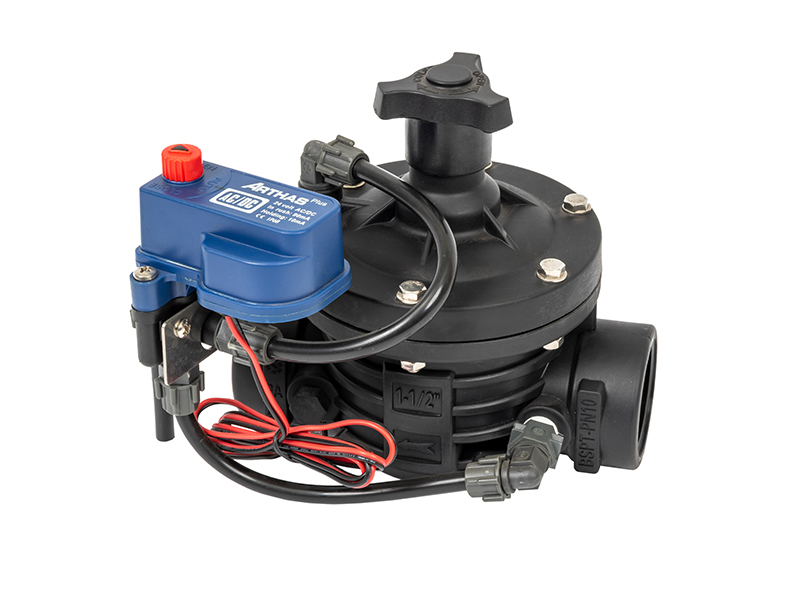
When electrical automation is the primary goal, hydraulic valves come equipped with a small electromagnetic coil. This setup integrates the electrical solenoid with the hydraulic pilot system. When an electrical signal—typically a 24V AC or a 9V DC latching pulse—is sent from a central controller, the solenoid opens or closes the pilot circuit. This in turn operates the main rubber diaphragm. A prime example is the 2-inch T-type solenoid control valve commonly used in modern garden and agricultural setups. This configuration acts as the backbone of smart farming, enabling remote, timer-based, or sensor-driven automated control without manual intervention.
While reducing valves protect downstream emitters, pressure sustaining valves monitor and protect the upstream infrastructure. They ensure that the pressure in the main line never drops below a predetermined minimum threshold. This proves vital for preventing the main pump station from entering a destructive run-out condition. If multiple field zones open simultaneously, the pump can spin too fast and damage its impeller, but a sustaining valve prevents this catastrophic failure.
The agricultural sector is currently undergoing a massive technological transformation. Driven by global water scarcity and the aggressive push for precision agriculture, recent industry analyses highlight a decisive shift. Purely mechanical, manually adjusted systems are rapidly giving way to fully automated, IoT-integrated water management networks.
Modern growers increasingly demand hardware that interfaces directly with cloud-based controllers and field sensors. Instead of watering on a rigid fixed timer, these smart systems read real-time soil moisture data, weather forecasts, and evapotranspiration rates. For instance, if a sudden rainstorm approaches, the central computer instantly sends a signal to the field valves to shut down. This level of responsiveness conserves thousands of gallons of water per event. Integrating rugged hydraulic mechanics with advanced digital intelligence is no longer a luxury reserved for mega-farms. It has rapidly become the baseline standard for commercial operations looking to maximize yield while minimizing resource waste.
Selecting the correct unit depends entirely on the physical and operational hurdles of the specific plot of land it will regulate. A mismatch here guarantees poor performance.
As water cascades down a steep elevation drop, gravity acts as an invisible pump. It naturally gains pressure, roughly 0.433 PSI per foot of elevation drop. Left unchecked, this leads to severe over-watering, uneven distribution, or violently burst pipes at the bottom of the hill. To counteract this, install a pressure reducing unit at the start of the downhill zone. This ensures that regardless of the steep drop or fluctuating pump pressure, the emitters at the lowest point of the valley receive a safe, perfectly uniform operating pressure.
On level ground, the primary requirement shifts away from complex pressure modulation. Instead, the focus moves toward general flow control and reliable automation. A standard hydraulic body equipped with a solenoid pilot is ideal here. This straightforward setup allows the farm manager to easily automate watering cycles using standard timers, ensuring consistent moisture delivery across flat topographies without overcomplicating the manifold.
Water traveling through thousands of feet of PVC pipe experiences immense friction against the inner walls. This results in significant pressure loss by the time it reaches the furthest corners of the property. For these distant zones, ensure the selected hardware has an exceptionally low friction loss rating. Irrigation engineers often recommend sizing up the valve slightly in these remote areas. A larger internal body minimizes any additional pressure drop across the mechanism itself.
Indoor growing environments demand extreme precision. They require frequent micro-watering cycles and gentle delivery for delicate seedlings. Highly responsive electric solenoid valves paired with precise pressure regulation are mandatory in this scenario. These units must open and close rapidly and reliably to accommodate the short, frequent pulses required by overhead greenhouse misting systems.
Proper sizing is an exact science. Field experience shows that guesswork during the design phase guarantees blown fittings and compromised yields.
Equipment must always be sized based on the specific flow demand of the zone, never by simply matching the diameter of the existing pipe. Forcing a high volume of water through a hydraulic control valve that is too small results in extreme pressure loss and dangerously high water velocity. This triggers cavitation, a localized pressure drop that creates violent vapor bubbles which aggressively erode the interior metal or plastic. Conversely, if a unit is too large for a low-flow zone, the diaphragm will barely open. This causes the internal rubber to chatter against the seat, leading to rapid mechanical wear and highly unstable pressure regulation.
Always verify the maximum allowable working pressure, often denoted as PN10 or PN16. This rating must safely exceed the absolute maximum peak pressure output of your main pump station. You must also factor in potential water hammer surges that occur during sudden system shutdowns.
Valves are typically available with flanged, threaded, or grooved connections. The choice depends entirely on your mainline material. Flanged connections are the heavy-duty standard for large diameter cast iron or HDPE mainlines, while threaded connections suit smaller PVC sub-mains in the field.
| Technical Parameter | Engineering Description | Primary Sizing Consideration |
|---|---|---|
| Flow Rate Capacity | The volume of water passing through the unit per hour or minute. | Must strictly match zone demand to avoid chattering or destructive cavitation. |
| Pressure Rating | The maximum allowable internal working pressure. | Must exceed the peak output pressure of the irrigation pump station. |
| Friction Loss | The natural pressure drop as water flows across the internal body. | Keep as low as possible, especially for distant or low-pressure field zones. |
| Connection Standard | Flanged, NPT/BSP threaded, or grooved ends. | Must ensure secure, leak-proof compatibility with existing PVC or HDPE pipes. |
The construction material profoundly impacts longevity, weight, and suitability for specific harsh environments.
Heavy-duty metal units, such as cast iron or ductile iron, offer extreme durability and high-pressure tolerance. They remain the standard choice for mainlines and large centralized pump stations. However, they are incredibly heavy, require heavy machinery to install, and are prone to internal rust if passing gravel scratches the protective epoxy coating.
In contrast, high-grade engineering plastics and glass-reinforced nylon models are highly corrosion-resistant, lightweight, and cost-effective. For example, a 2-inch T-type valve made from glass-reinforced nylon is entirely immune to rust. This makes it exceptional for systems that frequently inject liquid fertilizers, acids, or agricultural chemicals directly into the water stream. While their maximum pressure limits are slightly lower than ductile iron, they remain the undisputed preferred choice for distributed in-field zone control.
When upgrading agricultural infrastructure, selecting a reliable manufacturer is just as important as dialing in the technical specifications. Buyers should evaluate vendors based on strict, practical criteria. Look for comprehensive warranties, the immediate availability of spare parts including replacement rubber diaphragms and solenoid coils, and accessible technical support for troubleshooting complex pilot circuits.
For professional-grade agricultural solutions, operators must explore high-quality hardware that meets rigorous field requirements. Partnering with established suppliers ensures that the equipment will withstand the harsh, unforgiving environmental conditions of commercial farming. Baking sun, freezing nights, and dirty water will destroy inferior products. Quality hardware consistently delivers precise hydraulic performance season after season.
Even the most robustly engineered hardware requires routine maintenance to function optimally over decades of use. I always advise my crews to follow a few strict protocols.
First, never skip flushing the main pipelines before commissioning a new unit. Trench debris like PVC shavings, rocks, and mud will instantly puncture or tear a brand-new rubber diaphragm during the initial startup. Second, pay close attention to the pilot filter. Most hydraulic units feature a small inline filter on the external pilot tubing. Unscrew the small plastic housing, remove the stainless steel mesh, and rinse off the accumulated silt and algae at the start of every irrigation season. A clogged pilot filter prevents water from entering the upper chamber, causing the valve to fail open.
Winterization is another critical step. In regions experiencing freezing temperatures, water left inside the control chamber will expand into ice and violently crack the outer casing. Systems must be thoroughly drained or blown out with compressed air before the first hard freeze. Finally, if an automated unit fails to open, the issue is often electrical rather than mechanical. Use a standard multimeter to periodically test the resistance levels of the solenoid coil. This ensures it has not short-circuited or burned out due to a lightning strike or power surge.
Selecting the correct control hardware optimizes water distribution across your entire agricultural property. It turns a chaotic, wasteful watering schedule into a highly efficient, automated process. Carefully evaluating your unique field zones—from steep hillsides to distant flatlands—acts as the crucial first step. Calculating precise flow rates prevents expensive system damage and minimizes water waste. Furthermore, implementing pressure reducing features is absolutely critical for sloped terrains.
Taking the time to properly match technical specifications with field realities upfront consistently saves significant capital over time. Map out your field zones meticulously before making a purchasing decision. If you are ready to upgrade your irrigation infrastructure with professional-grade, glass-reinforced nylon or metal solutions, explore the comprehensive catalog at ARKA Irrigation to find the exact hardware tailored to protect your crops and boost your bottom line.
While regular manual gate or ball valves are cheaper upfront, they require intense, daily physical labor to open and close. Hydraulic units utilize the existing line pressure to operate, which allows for remote automation, precise pressure regulation, and seamless integration with smart farming controllers. Furthermore, manual valves cannot automatically regulate or stabilize pressure drops, putting downstream equipment at severe risk.
A unit that fails to close or leaks constantly is usually suffering from debris. A small pebble or a twig often gets trapped between the rubber diaphragm and the internal valve seat. Other common culprits include a physical tear in the diaphragm itself, or a clogged pilot control tube that prevents pressurized water from entering the upper chamber to push the seal down.
Yes, especially if your farm features severe elevation changes. While a Variable Frequency Drive efficiently controls the overall pressure at the centralized pump station, it cannot account for the localized pressure increases caused by gravity as water flows down steep hills. A reducing unit controls the pressure locally at the specific field zone, protecting fragile emitters at the bottom of the slope.
Never size based on your pipe diameter alone. You must calculate the total flow demand of all the emitters or sprinklers in that specific zone operating simultaneously. Once you have your total Gallons Per Minute or Cubic Meters Per Hour, consult the manufacturer's friction loss chart. Select a size where your required flow falls right in the middle of the recommended operating range to avoid both cavitation and chattering.
When properly sized and maintained, high-quality glass-reinforced nylon valves easily last 10 to 15 years in the field. The heavy-duty plastic body is immune to rust and chemical corrosion. The only components that typically require replacement are the internal rubber diaphragm and the electrical solenoid coil, both of which are inexpensive and easy to swap out during routine seasonal maintenance.
Most professional hydraulic hardware features a highly modular design. You can easily automate a manual unit by adding an electric solenoid base and a specialized pilot circuit to the existing body. This simple upgrade allows the hardware to receive standard 24V AC or 9V DC electrical signals from a central irrigation timer or smart controller, instantly modernizing your entire setup.


