
Views: 0 Author: Site Editor Publish Time: 2026-10-17 Origin: Site


Clogged emitters ruin crops. You install a brand-new irrigation system, turn on the pump, and watch the water pressure plummet. This scenario is an operator's worst nightmare. Clean water is non-negotiable for healthy plants, but skipping filtration entirely just leaves you battling blocked drip lines daily.
The core problem is a delicate hydraulic balancing act. You need water clean enough to prevent clogs. However, you cannot afford a drastic pressure drop—often referred to as head loss—that restricts the vital Gallons Per Minute GPM your fields desperately demand. The wrong hardware kills your flow rate and starves your crops when they need hydration the most.
Recent agricultural technology trends reveal a massive shift toward precision irrigation. With global water scarcity intensifying, modern growers prioritize high-efficiency systems maximizing yield per drop. We are seeing a surge in demand for advanced filtration setups guaranteeing zero flow restriction while handling heavy organic loads. Operators are abandoning basic, undersized housings. Instead, they invest in automated, high-capacity systems leveraging fluid dynamics to maintain constant pressure. This shift drastically reduces labor costs, eliminates water waste, and protects expensive downstream infrastructure.
In this comprehensive engineering guide, you will learn a highly effective sizing process. We will help you choose the right hardware today by matching the filter type, physical size, and mesh rating to your specific water source and unique flow requirements. This ensures optimal system performance without compromising hydraulic pressure.
Integrating a filtration unit is not merely about blocking dirt. It is a complex exercise in fluid dynamics. The primary objective is to protect the downstream components of your agricultural infrastructure without starving those same components of the hydraulic energy they require to function.
When water is forced through a porous barrier, friction naturally occurs. In fluid dynamics, this friction results in a phenomenon known as pressure drop or Delta P. Every unit introduces a baseline level of friction into the pipeline. A clean, properly specified housing might only cause a negligible pressure drop of 2 to 5 Pounds per Square Inch PSI. However, if an improperly chosen barrier is installed, the friction increases exponentially. As debris accumulates, the available pathways for water shrink. This causes a severe pressure drop.
Imagine walking your fields in mid-July only to discover the end of your drip tape is bone dry. The emitters have not failed. Your undersized filter has choked the flow, leading to uneven crop yields and dry zones in landscaping.
Undersizing the housing remains the most common cause of flow restriction. A unit with insufficient surface area forces the entire water volume through a tight bottleneck. This hydraulic choke point slashes both your flow rate and your operating pressure. An undersized unit reaches its maximum debris-holding capacity rapidly, restricting flow just minutes or hours after cleaning. Protecting your investment requires foresight. Faced with constant flow restriction, some operators make the catastrophic mistake of removing the internal element entirely. Without proper protection, particulate matter travels directly into the system, permanently clogging solenoid valves and ruining micro-sprinklers. Replacing an entire field of blocked tape costs exponentially more than investing in the correct hardware upfront.
The foundation of any robust design relies entirely on analyzing the raw water source. Water is not a uniform variable. It carries wildly different types of suspended solids depending on its origin. Identifying these contaminants is the mandatory first step before implementing any drip irrigation filtration strategy.
Municipal water is treated and pressurized before it reaches your property, generally making it the cleanest source available. Aging city infrastructure often introduces small particles of pipe scale, rust, or mineral sediment into the supply. Because this debris load is low and inorganic, municipal water requires minimal intervention to protect the system without causing flow restriction.
Well water presents unique subterranean challenges. Depending on the depth of the well and the aquifer's geology, pumps frequently pull up fine sand, silt, and grit. Some regions also battle iron bacteria, which is a slimy, rust-colored biological contaminant. If the wrong physical barrier is used on a sandy well, sharp inorganic particles wedge into the matrix, causing rapid flow restriction.
Surface water, such as ponds, lakes, rivers, and canals, is universally considered the most challenging source. Open bodies of water are highly biologically active. They contain heavy concentrations of organic matter like algae, moss, fish waste, and decomposing plant material. Organic matter behaves drastically differently than sand under pressure. If organic slime hits a standard flat screen, the water pressure extrudes the paste through the holes. This instantly blinds the surface and causes an immediate, total loss of water flow.
Once the water source is analyzed, the next critical phase is matching the contaminant type to the correct technology. Selecting the wrong physical mechanism guarantees a bottleneck. To make an informed decision, review this objective comparison of the primary options used in the agricultural and landscaping industries.
| Technology Type | Best Water Source | Primary Advantage | Flow Impact & Limitation |
|---|---|---|---|
| Screen | Municipal / Clean Wells | Cost-effective, excellent for hard inorganic grit. | High restriction risk if organics are present. Blinds quickly under heavy algae loads. |
| Disc | Ponds / Canals / Dirty Wells | True depth filtration. Traps massive organic loads without dropping pressure. | Requires higher initial investment but maintains stable GPM longer. |
| Sand Media | Heavy Surface Water | Unmatched capacity for processing hundreds of GPM in commercial farms. | Large physical footprint and requires backwash automation to maintain flow. |
Operating as a simple physical barrier, a screen filter forces water through a cylinder made of woven stainless steel mesh or molded plastic. Any particle larger than the precise geometric holes is trapped on the inside, while clean water passes through. They are highly effective at stopping hard, inorganic particles like sand. Because they rely strictly on two-dimensional surface filtration, organic matter like algae will smash against the mesh and blind it rapidly.
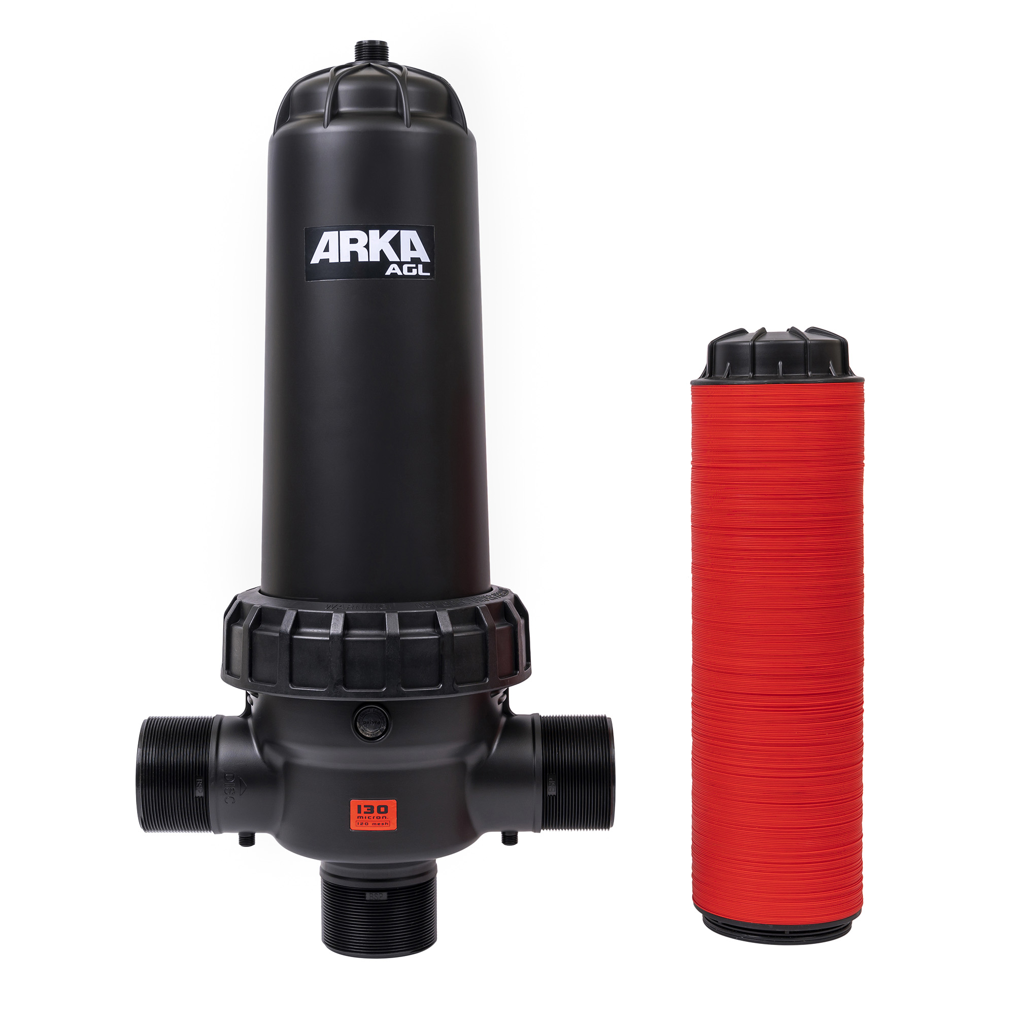
For water sources containing organic matter, a disc filter provides superior performance and prevents premature flow restriction. Instead of a single flat layer, this technology uses a stack of tightly compressed, color-coded plastic rings etched with microscopic grooves. When compressed by a central spine, these grooves intersect to create a complex, three-dimensional matrix. This design utilizes depth filtration, trapping particles throughout the entire depth of the stack rather than just on the surface.
To understand the engineering value, look at industry-leading specifications. For instance, a commercial-grade 3-Inch AGL Disc Filter designed for agricultural applications can handle high flow rates up to 50 cubic meters per hour. More importantly, it features a massive filtration surface area of 1195 square centimeters. This expansive surface area allows the unit to hold a significantly larger volume of algae and slime before the pressure drop becomes severe, making it the industry standard for ponds or canals.
For commercial agricultural operations moving massive volumes of highly contaminated water, a sand media filter is the ultimate heavy-duty solution. Water is pumped into large epoxy-coated steel or fiberglass tanks filled with crushed silica sand or basalt. As water percolates down through the deep bed, it traps massive amounts of both organic and inorganic debris. While they require a larger upfront capital investment, their ability to process massive flow rates without restricting pressure is unmatched for large-scale farms.
Centrifugal sand separators, often called hydrocyclones, are also vital pre-filtration devices. While not true filters because they lack a physical barrier, they use kinetic energy to create a vortex. This spins heavy particles like sand outward, allowing them to fall into a collection chamber. Removing ninety percent of heavy sand before the water reaches the primary housing prevents overwhelming clogs and protects your overall flow rate.
Selecting the physical housing is only half the equation. Specifying the exact level of filtration required is equally crucial. Engineers measure this in mesh and microns. Misunderstanding these metrics is a leading cause of localized flow restriction.
Mesh rating refers to the number of holes per linear inch of the material. A 120-mesh screen has 120 holes per inch. Therefore, the higher the mesh number, the finer the filtration. Conversely, a micron is a unit of measurement equal to one-millionth of a meter, measuring the actual physical size of the particle that can pass through. The lower the micron number, the finer the filtration.
Finding the Goldilocks zone is critical when selecting a mesh size. If the mesh is too coarse, such as a 40-mesh rating, debris passes right through and travels down the pipe. This dirt clogs the microscopic orifices of your drip emitters. Flow restriction happens at the plant level, which is incredibly expensive to fix. If the mesh is too fine, like a 200-mesh rating used on a relatively clean source, it catches microscopic dirt that would have safely passed through the emitters. Because it catches absolutely everything, it clogs incredibly fast, causing flow restriction at the source and requiring constant manual cleaning.
Always consult the specification sheet provided by the manufacturer of your drip tape. The industry standard baseline for standard drip setups is typically 120 to 150 mesh, which is equivalent to 130 to 100 microns. Micro-sprinklers often require slightly less stringent protection, usually around 80 to 120 mesh.
Even with the correct mechanism and mesh rating, installing a unit that is physically too small for your water volume will immediately throttle your system. Proper sizing requires basic mathematical calculations based on your system's output to select the right irrigation filter.
You must calculate the total flow rate to size the housing correctly. If your property is divided into multiple zones, calculate the flow rate for the largest single zone that operates at one time. First, identify the flow rate of a single emitter. Next, count the total number of emitters in that zone. Multiply the two numbers to find total Gallons Per Hour. Divide that number by 60 to convert to Gallons Per Minute. For example, one thousand emitters flowing at 0.5 Gallons Per Hour equals 500 GPH. Divided by 60, your system requires an absolute minimum flow of 8.33 GPM to function correctly.
Every reputable manufacturer provides a specification sheet detailing maximum flow capacities. A standard 3/4-inch housing might be rated for up to 12 GPM, while a 2-inch commercial unit might handle up to 120 GPM. You must ensure the maximum rating comfortably exceeds your required flow.
Engineers rarely design systems to operate at one hundred percent of their maximum capacity. To guarantee zero flow restriction and reduce maintenance frequency, proactively oversize your capacity by twenty to thirty percent. Returning to the previous calculation of 8.33 GPM, you should look for a unit rated for at least 11 GPM. A larger body contains a larger internal cartridge. More surface area means the water faces less friction as it passes through. This results in minimal pressure drop and significantly longer intervals between cleanings.
The final consideration in maintaining optimal flow rate is how accumulated debris is removed from the system. Flow restriction is a progressive issue. A setup may operate perfectly on day one but slowly choke over the following weeks as dirt builds up. As debris coats the matrix, the open area for water to pass through decreases. This increases water velocity through the remaining holes and forces softer organic debris deeper into the clog.
Manual setups are the standard choice for small to medium-sized operations or properties utilizing clean municipal water. When the system experiences a noticeable pressure drop, the operator must shut off the water supply, unscrew the housing, remove the internal cartridge, and physically wash it with a hose or brush. While they have a low initial purchase cost, they incur higher ongoing labor costs. Neglecting a manual unit on a dirty water source inevitably leads to severe flow restriction.
For commercial agriculture, remote locations, or systems drawing from heavily contaminated surface water, automatic self-cleaning configurations are highly recommended. These systems utilize a pressure-differential switch that constantly monitors water pressure at both the inlet and the outlet. When debris builds up and the pressure drops by a predetermined amount, typically around 7 PSI, the computer triggers a flush cycle. Valves shift to reverse the flow of water, aggressively cleaning the screens or decompressing and spinning the disc stacks to flush debris out of a discharge port. This entire process happens in seconds, often without interrupting the watering cycle.
Transitioning from theoretical knowledge to practical application requires a systematic approach. Selecting the correct equipment is an engineering decision based on empirical data regarding your specific environment. A poorly chosen unit will inevitably lead to severe pressure drop and premature failure of your emitters. Follow this evaluation process to maintain an optimal flow rate.
Protecting your downstream infrastructure is paramount to agricultural success. You do not have to sacrifice valuable water pressure to achieve clean lines. By matching the specific filtration technology to your unique debris profile and proactively oversizing your housing surface area, you get the best of both worlds: highly purified water and robust hydraulic pressure. This calculated engineering approach ensures consistent water distribution across your entire crop yield.
Evaluate your current setup today to identify hidden bottlenecks causing friction loss. Explore high-quality, zero-restriction filtration solutions at Arka-Irrigation to find the exact product specifications matching your unique flow requirements. Upgrading your hardware ensures your choices never compromise your system's vital hydraulic energy.
Always install the primary filtration unit BEFORE the pressure regulator. Pressure regulators contain highly sensitive internal components, including calibrated stainless steel springs and rubber diaphragms. If unfiltered water enters the regulator, a single grain of sand or a small buildup of mineral scale can lodge inside the mechanism. When this happens, the regulator may fail in the open position, allowing high-velocity mainline pressure to surge into your system. This will instantly rupture delicate drip tape and blow emitters off their fittings. Filters are structurally designed to withstand high static mainline pressure, serving as the first line of defense for all downstream hydraulic components.
A properly sized, brand-new housing should only register a pressure drop of 2 to 5 PSI. To monitor this accurately, install pressure gauges on both the inlet and outlet sides. If your inlet gauge reads 50 PSI and your outlet gauge reads 47 PSI, the flow is unrestricted. However, if a clean unit shows a pressure drop of 10 PSI or more right out of the box, the housing is severely undersized for your system's flow rate, and you are suffering from unnecessary friction loss.
Yes, installing two identical units in a parallel manifold configuration is a highly recommended engineering practice for large systems. When you plumb them side-by-side, you effectively split the total water volume between them. According to the principles of fluid dynamics, cutting the flow rate in half through a single unit exponentially reduces the friction loss. This setup doubles your total surface area, guarantees near-zero pressure restriction, and allows your system to run twice as long before requiring manual cleaning.
Cleaning frequency is entirely dependent on the biological and particulate load of your specific water source, making a strict calendar schedule unreliable. Instead, rely on empirical pressure data. Check the pressure differential between the inlet and outlet gauges. When the pressure drop increases by 5 to 7 PSI above its clean baseline, the media is becoming restricted and must be cleaned immediately. During peak summer months when drawing from a pond experiencing an algae bloom, this could mean cleaning daily. For clean municipal water, it may only require a quick rinse once per season.
A centrifugal sand separator is not technically a filter, as it contains no physical mesh, rings, or media bed. Instead, it is a hydrocyclonic pre-filtration device. Water enters the separator at a high velocity and is spun in a vortex. The centrifugal force throws heavy inorganic particles like sand to the outer walls, where they slide down into a collection chamber. Separators are highly effective for well water, removing up to ninety-eight percent of heavy sand before the water reaches your primary barrier. However, they are completely useless against organic matter like algae, as organics are too light to be separated by centrifugal force.
Using a flat screen for surface water is highly discouraged by professionals, regardless of how often you intend to clean it. Organic matter such as algae and biological slime does not behave like dirt; it acts like a paste. The moment the pump turns on, the hydraulic pressure will smash the algae into the microscopic pores of the stainless steel or plastic mesh. It can blind the surface in a matter of minutes, dropping your system pressure to zero. Furthermore, cleaning algae out of this specific mesh is incredibly difficult, often requiring harsh chemicals or a pressure washer, which can easily damage the delicate material.
Filter size is dictated by two separate metrics: flow capacity and mesh rating. First, calculate the maximum Gallons Per Minute your system requires by multiplying your total emitter count by the individual emitter flow rate. Choose a housing with a maximum capacity at least twenty percent larger than your required GPM to prevent pressure loss. Second, check your drip tape manufacturer specifications for the mesh rating. Most standard drip systems require a 120-mesh rating to protect the microscopic labyrinth inside the emitters from clogging.
Yes, every physical barrier introduces friction into a pipeline, which naturally causes a slight reduction in water pressure known as head loss. A properly engineered and correctly sized unit will only cause a negligible drop of 2 to 5 PSI when clean. However, if you install a unit that is too small for your flow rate, or if you allow debris to accumulate without cleaning it, the friction increases exponentially. This creates a severe bottleneck that will drastically reduce your operating pressure and starve your downstream emitters.


