
Views: 0 Author: Site Editor Publish Time: 2026-10-16 Origin: Site


Imagine walking through your agricultural rows during the peak of summer. You expect to see lush, thriving crops. Instead, you are met with a frustrating scenario. Wilting foliage, unexplained dry patches in the soil, and a skyrocketing water bill plague your field. More often than not, this agricultural heartbreak stems from a single, unseen issue. Your drip emitters are completely clogged.
Drip systems rely on microscopic orifices to regulate water flow with pinpoint precision. This makes them inherently vulnerable. These tiny labyrinths easily trap dirt, algae, sand, and mineral deposits. A clogged system does not just fail to hydrate your plants. It quietly wastes water by altering system pressure, forcing leaks elsewhere, and ultimately damaging expensive crops.
The most effective, empirical solution to this vulnerability is the installation of an irrigation filter. Serving as the primary physical safeguard for your water lines, a proper filtration setup is significantly more cost-effective than replacing miles of ruined drip tape. This comprehensive guide explores the mechanics of how these devices operate, how to select the correct type for your specific water source, and the practical steps for maintaining your equipment to ensure flawless, long-term performance.
Clogging in micro-irrigation is rarely a sudden, catastrophic event. Rather, it is a gradual accumulation of organic and inorganic matter that slowly strangles your system. On a practical level, the most common culprits include inorganic sediments like sand, silt, and clay. These are frequently drawn from agricultural wells. Furthermore, organic matter such as the slick green sludge of algae and bacterial slime thrives in surface water sources like retention ponds.
When these elements bypass a compromised barrier, they lodge securely within the narrow pathways of the emitters. The consequences extend far beyond a single dehydrated plant. When certain emitters clog, localized soil moisture drops dramatically. This translates directly to reduced crop yields in farming environments. Conversely, plants situated near the beginning of the line may actually drown. The altered flow dynamics force excess water through the remaining open orifices.
Additionally, clogs create severe backpressure within the polyethylene tubing. This unintended hydraulic spike often results in blowouts at weak fittings, leading to significant water waste. Diagnosing and repairing this damage is incredibly labor-intensive. It requires a technician to physically walk the wet lines, identify the dry zones, surgically cut out the defective micro-emitters, and splice in new ones. This tedious process drains valuable time and operational resources.
Looking at current agricultural trends, the global shift toward precision farming has made advanced water treatment an absolute necessity. Escalating water scarcity issues force commercial growers and residential landscapers to rely heavily on reclaimed wastewater or effluent water sources. Industry data indicates that utilizing these alternative supplies introduces exceptionally high biological and particulate loads into the piping infrastructure.
Consequently, modern agricultural engineering now treats multi-stage drip irrigation filtration as foundational infrastructure. High-efficiency drip systems engineered to combat modern drought conditions would fail within weeks without intercepting these heavy suspended solids at the source.
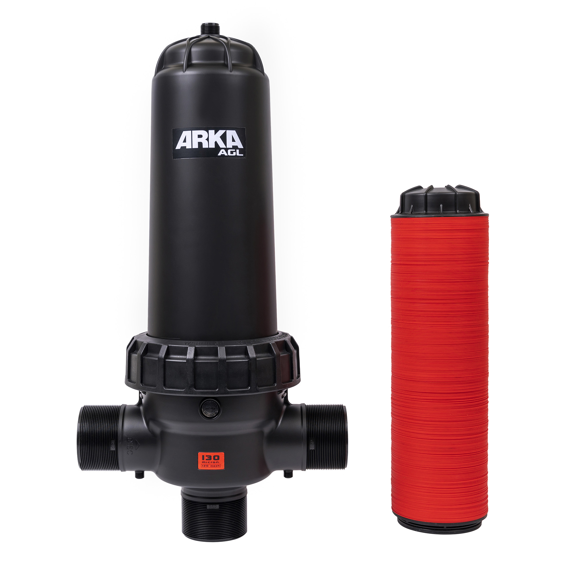
At its core, this technology relies on the straightforward principles of mechanical separation. The unit acts as a physical barrier installed directly in the main water supply line. As pressurized water enters the housing, it is forced to navigate through microscopic pores, grooves, or media beds. Because these pathways are intentionally sized to be smaller than the orifices of the downstream emitters, suspended solids are trapped within the matrix. Only purified liquid proceeds into the delicate network.
Take professional-grade equipment like the ARKA 3-Inch AGL Disc Filter as a prime example. Engineered with a robust polyamide housing, it utilizes tightly stacked, grooved rings to intercept particulate matter. By capturing debris directly at the source, the hardware ensures the final delivery points remain entirely unobstructed. This consistency is critical for maintaining steady hydrodynamic pressure across the entire watering zone. When the lines are clean, a plant at the far end of a 200-foot run receives the exact same volume of water as a plant located inches from the main valve.
Selecting the correct technology is a foundational decision. It must be dictated by objective data regarding the biological and particulate load of your primary water source, rather than just budget constraints. Below is a practical breakdown to guide your engineering choices.
| Filter Type | Best Water Source | Primary Target Debris | Maintenance Level |
|---|---|---|---|
| Screen Filter | Municipal City Water / Clean Wells | Hard inorganics like sand, pipe rust, and grit | Low to Medium |
| Disc Filter | Ponds, Lakes, Reclaimed Wastewater | Soft organics like algae, slime, plus heavy sand | Medium |
| Sand Media Filter | Open Agricultural Canals | Massive volumes of heavy organics and silt | High / Automated |
When dealing with relatively clean municipal supplies, a screen filter often serves as the first line of defense. It consists of a rigid plastic or stainless-steel mesh cylinder housed within a protective casing. Water flows from the outside of the screen to the inside, leaving hard debris trapped on the exterior surface.
These units are highly cost-effective and excel at isolating hard particles like pipe rust and coarse sand. However, they utilize a two-dimensional surface area. As a result, they are easily overwhelmed by soft organic matter. Algae and bacterial slime can quickly smear across the flat mesh, blinding the pores and causing rapid pressure drops.
For greater versatility and resilience, a disc filter utilizes a stack of tightly compressed, color-coded plastic rings. Each ring features microscopic diagonal grooves etched into its surface. When stacked and compressed by the central spine, these intersecting grooves create a deep, three-dimensional filtration matrix.
This structural depth makes it exceptionally effective at trapping soft, squishy organic materials that would normally smear on a flat screen. Advanced models easily handle higher flow rates and are remarkably easy to backflush. For property owners drawing water from lakes or reclaimed sources, investing in this specific technology prevents aggressive biological clogging.
Operating on a much larger scale, a sand media filter consists of pressurized steel or fiberglass tanks filled with crushed silica or basalt. Water is forced downward through this thick bed of granular media. The matrix captures massive volumes of organic and inorganic debris before the purified water exits through the bottom manifold.
This represents the gold standard for highly contaminated environments like open agricultural canals. While offering immense holding capacity, these systems require a large physical footprint and necessitate complex automated backwashing valves. Therefore, they are generally considered overkill for standard light-commercial landscapes.
Understanding the metrics used to measure porosity is essential for protecting your system without unnecessarily restricting water flow. Manufacturers universally rate these products by either mesh or micron sizes. Understanding the inverse relationship between the two is vital.
The mesh rating refers to the number of threads per linear inch on a screen. A higher mesh number indicates a finer barrier because more threads are packed into the same space. Conversely, a micron is a literal unit of length measuring the actual size of the hole itself. A lower micron number indicates a finer barrier. To put this into perspective, a 120-mesh rating is roughly equivalent to 125 microns.
When designing a micro-irrigation layout, standard industry practice dictates that most drip tape requires a minimum filtration level of 120-mesh. This specific density effectively traps microscopic particles large enough to bridge together and block standard emitter pathways. Crucially, you must consult the technical specifications provided by your specific emitter manufacturer. Installing an excessively fine 200-mesh unit on a relatively clean city water line will result in unnecessary pressure restrictions and force you into a frustrating cleaning schedule.
The physical placement of the hardware within your system architecture dictates both its effectiveness and its operational lifespan. Haphazard installation easily leads to bypassed debris or catastrophic damage to sensitive downstream components.
To ensure proper hydraulic function, components within a professional valve manifold must be installed in a strict sequential order. The water must first pass through the control valve, followed by the backflow preventer. Immediately after the backflow device, the filtration unit must be installed. This is then followed by the pressure regulator, and finally, the drip tubing adapter.
Placing the barrier before the pressure regulator is a non-negotiable rule. Pressure regulators contain delicate internal springs and rubber diaphragms highly susceptible to sediment fouling. Upstream placement simultaneously protects the expensive regulator and the downstream emitters. Best practices demand installing the unit above ground or inside a sufficiently large subterranean valve box. Burying the hardware in dirt guarantees neglect, ultimately leading to total system failure.
Even the most advanced, commercially rated hardware remains entirely dependent on routine human intervention. Neglecting to clear trapped debris restricts available pathways for water, creating a severe pressure drop that starves your plants of moisture.
The most empirical method for tracking internal buildup is differential pressure monitoring. By installing liquid-filled pressure gauges immediately before and after the housing, you can objectively monitor head loss. A differential of 5 to 7 PSI between the inlet and outlet gauges is the definitive scientific indicator that the matrix has reached its holding capacity and requires immediate flushing.
When it is time to clean a standard mesh unit, begin by isolating the system. Turn off the main water supply to depressurize the line safely. Carefully unscrew the outer canister. Extract the cylindrical mesh and rinse it thoroughly under a high-pressure stream of clean water. If you feel gritty mineral scale, gently scrub the surface with a soft-bristle nylon brush. Never use harsh wire brushes, as they will create micro-tears in the delicate mesh.
Maintaining a grooved ring system requires a slightly different approach. After depressurizing the line and removing the internal cartridge, loosen the tension nut located at the top of the central spine. This crucial step allows the tightly stacked rings to decompress and separate. Hold the loosened cartridge under running water and agitate the rings. The water will effortlessly wash away trapped organic slime from between the microscopic grooves. Once clean, retighten the tension nut to compress the matrix back into a solid cylinder and reinstall it.
Components operate under constant hydrostatic stress and are continuously bombarded by abrasive particulates. Over time, physical degradation is an unavoidable reality. Knowing exactly when to replace or upgrade your equipment is vital for maintaining systemic integrity.
During your routine cleaning schedule, inspect the internal elements with a critical eye. Watch for hairline cracks in the outer plastic housing caused by UV exposure or winter freezing. These can lead to explosive blowouts under pressure. For mesh models, look for tiny separations in the seams. Even a millimeter-wide tear allows enough sediment through to destroy dozens of emitters. If you notice warped rings or a damaged central spine that prevents proper compression, the cartridge must be retired.
Beyond physical wear, a fundamental change in your water supply necessitates a mandatory hardware upgrade. If a property transitions from clean municipal city water to an untreated agricultural well, attempting to use a basic screen unit will result in immediate failure. The sudden influx of heavy sediment demands upgrading to a more robust, three-dimensional disc system to handle the newly introduced biological load.
A proper physical barrier is not merely an optional accessory. It is the beating heart of a healthy, efficient drip system. By intercepting microscopic debris at the source, it prevents the slow, silent clogging that ruins micro-emitters and devastates plant life.
Taking the time to evaluate your specific water source and matching it with the appropriate technology ensures your investment operates at peak efficiency. When paired with a consistent maintenance routine, this relatively small piece of equipment saves countless hours of frustrating labor and conserves thousands of gallons of water. Ready to protect your agricultural yields and landscaping investments? Explore the professional-grade solutions at ARKA Irrigation to find the exact filtration hardware engineered for your specific field conditions.
Technically, a system will flow water without one initially, but agricultural professionals highly discourage it. Without a physical barrier, microscopic debris, minerals, and algae inevitably and rapidly clog the tiny orifices of the emitters. This leads to uneven watering, localized plant death, and costly system replacements.
A screen unit uses a single, flat layer of mesh to catch hard, inorganic debris like sand, making it ideal for clean city or well water. In contrast, a disc unit utilizes a stack of compressed, grooved rings to create a deep, three-dimensional filtration matrix. This allows it to trap both hard debris and squishy organic matter like algae without immediately clogging, making it vastly superior for surface water sources.
For standard drip tape and micro-emitters, industry guidelines strongly recommend a 120-mesh rating, which translates to roughly 125 microns. This specific density effectively blocks particulates large enough to bridge together and plug the emitter pathways without causing unnecessary flow restriction.
The most accurate method is checking the differential pressure using gauges installed before and after the unit. A pressure drop of 5 to 7 PSI indicates it is time to clean. Visually, if you notice a significant reduction in water output at your emitters or dry patches in your soil, your system is likely choked with debris.
The required cleaning frequency depends entirely on water quality and usage rates. City water setups may only require a quick rinse once or twice a season. However, well or pond water systems demand weekly or bi-weekly maintenance. Always inspect and clean the unit if you notice a visible drop in water pressure.
No. Standard mechanical barriers are designed exclusively to remove suspended physical solids, not dissolved minerals. To prevent calcium buildup or hard water scale from calcifying inside your drip lines, you must utilize specialized water softening treatments or perform periodic chemical line flushing in addition to your standard mechanical protection.


