
Views: 0 Author: Site Editor Publish Time: 2026-10-15 Origin: Site


Are overflowing tanks causing costly water damage? High inlet pressure often overpowers standard float valves. This leads to severe operational inefficiencies and frustrating maintenance cycles. An equilibrium type float valve solves this inherent flaw. It balances internal hydraulic forces for precise, effortless control.
This comprehensive guide breaks down exactly how this mechanism works. We will explore its mechanical benefits, real-world applications, and the critical criteria required to specify the correct unit for your infrastructure.
An equilibrium type float valve is a specialized, mechanically actuated device engineered to regulate the flow of water into a reservoir or holding tank. Its primary function is to remain open while the water level drops and to seal completely and securely when a predetermined maximum water level is reached. Basic mechanical stoppers rely entirely on the physical upward force of a buoyant object. This advanced unit uses internal fluid dynamics to assist the closing process instead. By utilizing the pipeline's own fluid kinetic energy to seal the mechanism, it serves as a highly resilient water level control valve suitable for rigorous industrial, municipal, and agricultural applications.
Standard and equilibrium designs handle incoming mains pressure very differently. Traditional float assemblies rely solely on the buoyancy of a large float ball pushing a lever arm to force a rubber seal against the incoming water stream. Consequently, if the inlet pressure is too high, the raw force of the water pushes the seal open. This inevitably causes the tank to overflow.
In contrast, an equilibrium type float valve features a balanced internal chamber. The incoming water pressure is equalized on both sides of a moving plunger or piston. Because these hydraulic forces cancel each other out, the float and lever mechanism only need to exert a fractional amount of force to slide the piston and shut off the flow. This fundamental design shift makes the equilibrium valve exceptionally stable. It allows the unit to thrive in high-pressure environments where standard alternatives would rapidly fail.
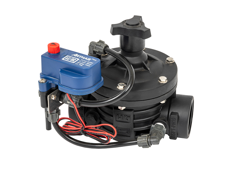
The operation of an equilibrium type float valve is a masterclass in practical hydraulic engineering and pressure differentials. The process unfolds across three distinct mechanical phases.
Valve Opens: When the water volume in the tank decreases, the float lowers accordingly. This downward movement pulls the lever arm, which in turn opens a small internal pilot port or pulls the main piston away from the seat. Instantly, water is permitted to flow through the main body and into the reservoir.
Pressure Equalization: As fluid rushes through the unit, internal chambers dictate the movement of the water. A specific volume is directed behind the internal piston or diaphragm. Because the surface area on the back of the piston is slightly larger than the front, the internal pressure begins to equalize. The mechanism does not have to fight the incoming kinetic energy of the water. It elegantly harnesses that energy to maintain structural balance.
Valve Closes: Picture a large municipal tank filling during a quiet midnight period. As the tank fills, the float rises synchronously with the water level. Because the internal pressure is already balanced in a state of equilibrium, the lever arm requires only a tiny fraction of upward mechanical force to close the pilot port. Once that port is sealed, hydraulic pressure rapidly builds behind the piston, forcing the main seal firmly against the valve seat and halting the flow entirely.
Water hammer, known mathematically as hydraulic shock, occurs when a fluid in motion is forced to stop or change direction suddenly. This creates a violent pressure wave that can rupture pipe joints and obliterate infrastructure. Standard float valves often snap shut abruptly as turbulent water ripples push the float up rapidly. The equilibrium design mitigates this risk entirely. Its pressure-balanced architecture ensures a smooth, proportional, and gradual closing action. As the water level nears the target line, the flow is slowly throttled. This prevents any sudden halting of fluid and completely eliminates destructive shockwaves.
Understanding the anatomy of this equipment is essential for proactive maintenance and proper specification. Every component must be manufactured to high tolerances to ensure leak-free operation.
This acts as the primary sensor of the system. Typically constructed from durable polyethylene, copper, or stainless steel, the float rests on the surface of the water. The lever translates the vertical movement of the float into the horizontal or vertical mechanical force required to actuate the pilot. In an equilibrium system, the lever arm can be significantly shorter and the float much smaller than those found in traditional setups. Less brute force is required to achieve a watertight seal.
This component is the true heart of the equilibrium design. Depending on the specific model and manufacturer, the unit will utilize either a sliding metallic piston or a heavy-duty flexible diaphragm. This part houses the internal chambers and ports that allow water pressure to equalize. It acts as a highly reliable hydraulic control valve mechanism, ensuring that the main elastomer seal glides smoothly toward the seat without chattering or vibrating under high flow velocities.
The main body provides the robust structural housing for the internal components and must withstand the maximum static and dynamic pressures of the network. Common materials include epoxy-coated ductile iron for large municipal applications, stainless steel for potable water, and heavy-duty reinforced nylon for agricultural irrigation setups. The valve seats are typically lined with resilient elastomers like EPDM or NBR to guarantee a watertight seal upon closure.
Facility managers and engineers frequently face the decision of whether to replace standard mechanical float valves with equilibrium models. While the initial capital expenditure of an equilibrium unit is generally higher, the long-term operational benefits heavily outweigh the upfront investment.
| Feature and Capability | Standard Mechanical Float Valve | Equilibrium Type Float Valve |
|---|---|---|
| High-Pressure Handling | Poor. Prone to leaking or being blown open by mains pressure. | Excellent. Internal balancing neutralizes high inlet pressure. |
| Water Hammer Risk | High. Sudden closure causes damaging hydraulic shock. | Low to None. Proportional closing mechanism prevents shockwaves. |
| Float Size Requirement | Large. Requires massive floats and long levers to generate force. | Compact. Requires minimal buoyancy force to actuate the pilot. |
| Maintenance Frequency | High. Mechanical strain leads to rapid wear of seals and pivot pins. | Low. Balanced forces reduce mechanical stress and prolong lifespan. |
| Flow Rate Capacity | Limited. High flow causes severe vibration and chattering. | High. Stable operation even at maximum pipeline flow velocities. |
In industrial settings, municipal water mains can easily deliver water at pressures exceeding 10 bar. A standard unit simply cannot hold back this immense force once the tank is full, leading to continuous weeping and eventual flooding. Equilibrium models thrive in these harsh conditions. They ingeniously utilize the high pressure to create an even tighter, more secure seal.
Recent market analyses regarding global fluid management indicate a decisive shift toward smart, sustainable infrastructure. As global water scarcity intensifies and municipal grids age rapidly, facility managers are increasingly abandoning traditional mechanical valves in favor of high-efficiency equilibrium designs. This ongoing trend is primarily driven by strict regulatory pushes to minimize non-revenue water loss and slash the exorbitant maintenance overhead associated with aging piping networks. Replacing outdated hardware with equilibrium technology is now a baseline standard for modern facility upgrades.
Municipal water distribution networks rely on massive storage reservoirs to maintain pressure and steady supply during peak morning and evening demand. Equilibrium mechanisms ensure these reservoirs fill efficiently without overflowing. They remain completely unbothered by the violently fluctuating pressures from primary pumping stations.
Cooling towers in large commercial skyscrapers lose significant volumes of water through evaporation and drift. Maintaining a precise water level in the cooling tower basin is absolutely essential to prevent the system's expensive circulation pumps from running dry and cavitating. These valves provide the continuous, stable top-up required for optimal HVAC efficiency.
Large-scale agricultural operations often utilize intermediate holding tanks to mix liquid fertilizers or store water before it is distributed to the fields. These rural systems frequently experience massive pressure spikes when large diesel irrigation pumps cycle on and off. Equilibrium designs protect these holding tanks from overflowing during unpredictable pressure surges.
An equilibrium type float valve rarely operates in total isolation. In professional fluid management engineering, it is typically deployed as part of a broader hydraulic ecosystem designed to protect infrastructure and optimize flow rates.
Extreme or wildly fluctuating pressures can cause premature wear on the internal elastomer seals over time. Installing a pressure reducing valve upstream from the float mechanism is a standard best practice. This upstream device steps down the turbulent, high mains pressure to a stable, manageable level. It ensures the equilibrium unit operates within its most efficient design parameters, extending its life and ensuring whisper-quiet operation.
When a massive reservoir begins to fill, the equilibrium valve opens fully, allowing maximum flow. In some networks, this sudden draw of water can cause a severe pressure drop in the main pipeline. This inadvertently starves other facilities or critical equipment of necessary water pressure. By integrating a pressure sustaining valve on the main line, engineers can ensure that the float valve only draws water when the primary network has surplus pressure. If the main line pressure drops below a critical setpoint, the sustaining unit restricts flow to the tank, prioritizing the broader network's stability.
Selecting the correct unit is a critical engineering decision that directly impacts the operational efficiency and safety of your water storage infrastructure. A poorly specified model can lead to inadequate flow rates, premature mechanical failure, or severe pump cavitation. To ensure optimal performance, buyers must evaluate sizing, pressure ratings, and material compatibility.
One of the most common errors in fluid management is sizing a component based solely on the existing pipe diameter. While matching the flange or thread size is necessary for installation, the internal flow capacity must align with the specific demands of the reservoir. For example, a 2-inch T-type valve configuration provides excellent flow dynamics for mid-sized agricultural tanks. Engineers must calculate the required flow coefficient, representing the volume of water that will pass through at a specific pressure drop. Always consult the manufacturer flow characteristic charts to ensure the unit operates within its optimal range.
The pressure rating must exceed the maximum static and dynamic pressures of your water supply line. Many high-quality agricultural models feature an operating pressure range of 0.1 to 1.0 MPa, ensuring stable operation under typical irrigation pump loads.
The construction material dictates resistance to corrosion, mechanical stress, and temperature fluctuations. Ductile iron with a fusion-bonded epoxy coating is the industry standard for municipal potable water. For aggressive environments or agricultural setups exposed to fertilizers, reinforced nylon or heavy-duty engineering plastics offer superior resistance to chemical degradation. Ensure the internal elastomers are matched to the fluid medium, especially if the water contains trace chemicals or debris.
Even the most robustly engineered equipment requires proactive maintenance to guarantee uninterrupted service. Implementing a structured maintenance schedule prevents unexpected downtime and extends the operational lifespan of the hardware.
Facility managers should implement a visual and operational inspection schedule on a quarterly basis. Key actions include checking the float integrity for physical damage or water ingress. A compromised float will lose buoyancy, preventing closure and leading to immediate overflow. Verify the lever arm alignment to ensure it connects to the piston perfectly straight and moves without friction. Observe the unit while it is in the fully closed position to look for continuous dripping from the discharge port, which indicates a worn primary seal.
Waterborne particulates, sediment, and mineral deposits can accumulate inside the equalization chambers over time. Because this design relies on precise internal fluid balancing, blockages in the narrow pilot ports or mineral scaling on the piston can cause the mechanism to stick. For systems utilizing hard water, isolate the water supply, carefully remove the cover, and extract the piston assembly annually. Use a non-abrasive descaling solution and a soft-bristled brush to dissolve mineral buildup.
| Operational Symptom | Potential Root Cause | Recommended Corrective Action |
|---|---|---|
| Fails to close completely | Debris trapped in the seat, punctured float, worn internal piston seal. | Isolate supply, flush out debris. Replace float immediately if waterlogged. Install a new seal kit. |
| Fails to open | Upstream isolation valve is closed, mineral scaling has seized the piston, float arm is obstructed. | Verify upstream valves are open. Disassemble, descale, and lubricate the piston. Clear physical obstructions. |
| Chatters or vibrates during closure | Inlet pressure wildly exceeds specifications, flow rate is too low for the oversized valve. | Install a pressure regulating device upstream. Re-evaluate sizing and consider a smaller unit. |
By adhering to these stringent maintenance protocols, industrial and agricultural operators can ensure their water level management systems remain highly responsive and structurally sound for decades.
An equilibrium type float valve stands as a highly reliable, mechanically superior solution for maintaining stable water levels safely. By ingeniously balancing internal hydraulic forces, this stability prevents costly water damage over time, effectively eliminates destructive water hammer, and drastically reduces mechanical wear compared to traditional lever units. Proper specification and routine maintenance ensure long-term cost savings and uninterrupted operational flow. Browse the extensive catalog at Arka Irrigation to find your ideal mechanism, contact our engineering team for expert sizing assistance, or request a quote today to upgrade and future-proof your water system.
The fundamental difference lies in how they manage hydraulic force. A standard mechanical float valve relies entirely on the upward buoyancy force of the float ball to physically push a stopper against the incoming water pressure. If the inlet pressure is exceptionally high, the water can force the stopper open, overcoming the float buoyancy and causing the tank to overflow. An equilibrium float valve features a specialized internal chamber. When water enters, it is channeled to both the top and bottom of the internal piston or diaphragm, equalizing the hydraulic pressure on both sides. Because the incoming water pressure is effectively neutralized by this balanced design, the float ball only needs to exert a very small amount of force to move the piston and close the unit.
Yes, it is highly effective at preventing water hammer, which is mathematically known as hydraulic shock. Water hammer occurs when a high-velocity flow of water is suddenly forced to stop by a fast-closing stopper. The kinetic energy of the moving water instantly converts into a severe pressure spike that travels back through the piping system, potentially rupturing joints and damaging pumps. Because an equilibrium mechanism is directly linked to the rising water level in the reservoir, its closure is inherently gradual and proportional. This modulated, slow-closing action gently decelerates the water column in the supply line, dissipating the kinetic energy safely and entirely eliminating the risk of destructive pressure shockwaves.
The maximum safe operating pressure depends entirely on the specific engineering standards, materials, and flange ratings of the chosen model. These units are specifically designed for high-pressure scenarios that would instantly destroy standard lever units. Commercially available models typically start with a Nominal Pressure rating of 10 bar, approximately 145 psi, of continuous pressure. More robust industrial models are rated for 16 bar. For extreme municipal or mining applications, specialized cast steel or heavy-duty ductile iron models can be manufactured to withstand 25 bar.
It is not always strictly necessary, but it is considered a highly recommended engineering best practice in certain volatile scenarios. If your main supply line pressure is relatively stable and remains well below the maximum rated pressure of the equilibrium unit, it will function perfectly on its own. However, if your facility is connected to a municipal grid that experiences wild pressure fluctuations, or if the static pressure occasionally exceeds the maximum threshold, you must install a pressure reducing device upstream. This will condition the incoming water, providing a stable, safe pressure environment. Additionally, if filling your large reservoir causes a massive pressure drop in the rest of your facility, you may also need a sustaining device on the main line to ensure other critical processes are not starved of water.
Adjusting the water level is typically a straightforward process. Most equilibrium valves feature an adjustable linkage or a sliding mechanism on the float arm itself. By loosening the adjustment screw or repositioning the float ball further down the arm, you can set the exact point at which the valve begins to close. Some modern models also include a fine-tuning screw directly on the pilot valve. Always make small adjustments and observe a full fill cycle to ensure the tank shuts off precisely at the desired high-water mark.
Continuous leaking, often referred to as weeping, is usually caused by debris trapped between the main elastomer seal and the valve seat. Even a tiny piece of grit or mineral scale can prevent the piston from seating perfectly flush. Another common cause is a worn-out internal diaphragm or O-ring that fails to hold the equalized pressure, causing the valve to slightly bypass water. Finally, check the float ball itself. If the float is punctured and waterlogged, it will not generate enough buoyancy to trigger the pilot port closure.


