
Views: 0 Author: Site Editor Publish Time: 2026-10-22 Origin: Site


How do you control high fluid pressure off-grid? Imagine a remote agricultural field or a rugged industrial site miles away from the nearest power pole. These environments lack safe electricity. Standard motorized actuators become completely useless here. When the grid fails, engineers must rely on the physics of fluid dynamics.
In this guide, we explore the solution for managing intense pipeline forces without a single kilowatt of external power. We break down how self-powered mechanical systems regulate flow. They ensure absolute safety and precision in the most unforgiving environments.
At its core, this specialized mechanical device controls flow, pressure, and direction within a piping network. The fundamental distinction of this unit lies in its actuation method. Most modern industrial components rely on motorized actuators or stable electrical grids to function. A true self-operated hydraulic unit is distinctly different. It requires absolutely zero external power. You need no batteries, no solar panels, and no complex wiring.
Instead, it extracts kinetic and potential energy directly from the flowing fluid. Procurement teams specify these devices for bottom-of-funnel infrastructure projects where failsafe reliability is non-negotiable. Relying on electrical actuation introduces unacceptable operational risks in hazardous environments or regions prone to power outages. By utilizing the media internal pressure to physically open and close, these mechanical marvels offer a robust solution. They drastically reduce both initial capital expenditure and long-term operational costs.
Looking at the broader landscape of civil engineering, there is a clear shift toward decentralized and climate-resilient infrastructure. Global water scarcity forces municipalities and massive agricultural conglomerates to tap into remote water sources. These new wells and reservoirs often sit miles beyond the reach of stable electrical grids.
Consequently, the market for self-actuating mechanical valves is experiencing a massive renaissance. While digital twins and AI-driven leak detection dominate headlines, the physical backbone of modern water management remains purely mechanical. A hybrid approach is emerging as the dominant trend today. Engineers increasingly pair robust mechanical valves with low-power IoT sensors. This setup allows the mechanical body to perform the heavy lifting of pressure regulation using zero electricity. Meanwhile, the attached sensor transmits flow data back to a cloud dashboard. This synergy reduces costs and aligns with global initiatives to lower the carbon footprint of heavy industrial operations.
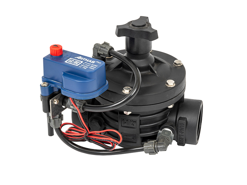
Grasping the operation of a self-powered regulator requires a basic understanding of fluid dynamics. The entire mechanism relies on a continuous mechanical feedback loop. This loop is driven by the physical principles of force, pressure, and surface area.
Water entering a pipeline carries intrinsic static pressure and kinetic energy. A self-actuated unit purposely redirects a small, controlled fraction of this incoming liquid into a dedicated upper chamber. By channeling upstream line pressure into this confined space, the system harnesses the fluid own energy. This performs the heavy lifting required to move the internal sealing mechanism against the rushing flow.
Physical movement inside the main body is typically governed by a diaphragm valve architecture. Fluid from the upstream pipeline enters a control chamber located directly above a flexible, heavy-duty rubber membrane. The physics governing this action are based on a simple equation. Force equals pressure multiplied by area.
Specifically, the surface area of the flexible membrane is intentionally designed to be significantly larger than the surface area of the valve seat below it. Even if the fluid pressure pushing up from the pipeline matches the pressure pushing down from the control chamber, the larger surface area of the upper membrane generates a substantially greater downward force. This differential force physically pushes the seal down and locks the passage shut. To initiate opening, fluid must evacuate from that upper chamber. This allows the upward pipeline pressure to overpower the downward force and lift the seal.
If the main body is the muscle, the pilot system serves as the brain. This pilot circuit consists of a smaller, highly sensitive sub-valve and external tubing attached to the main housing. Continuously sensing minute changes in downstream conditions, the pilot reacts based on the mechanical tension of a manually calibrated spring. It automatically adjusts the volume of water trapped inside the main chamber. By modulating the exact rate at which water enters or exits this space, the pilot ensures the main seal opens or closes proportionally. This locks in the exact desired setpoint without any digital intervention.
Upstream pressure fluctuates wildly in countless engineering applications. Erratic pump cycling, sudden elevation changes, and varying municipal demands all contribute to this instability. However, downstream equipment requires a steady, low-pressure feed to operate safely without rupturing.
A hydraulic pressure reducing valve is specifically configured to solve this exact problem through dynamic mechanical equilibrium. The operational sequence occurs in real-time, completely devoid of electronic sensors.
When downstream demand increases, the downstream pressure plummets below the target setpoint. Instantly, the calibrated spring in the pilot overcomes the weakened fluid resistance and pushes the pilot open. This action rapidly drains fluid out of the main upper chamber faster than it can be replenished. Consequently, the main seal lifts higher. This allows a larger volume of fluid and pressure to pass through to the downstream side to meet the new demand.
Conversely, when downstream demand decreases, the downstream pressure spikes. This sudden surge travels backward through the pilot sensing tube. It overpowers the pilot spring and forces the pilot shut. Fluid is subsequently trapped and forced back into the main chamber, multiplying the downward force. The main seal slowly modulates downward, restricting the flow path and effectively choking the downstream pressure back to a safe level.
Ultimately, this continuous, autonomous modulation maintains an incredibly stable downstream environment. It effortlessly absorbs upstream shockwaves and varying flow rates.
The long-term reliability of a self-operated fluid network depends entirely on the precision manufacturing of several distinct, heavy-duty components. A failure in any single part compromises the entire mechanical loop.
The Main Valve Body: This serves as the physical fortress. It is designed to withstand extreme hydraulic shear forces and environmental degradation. For agricultural uses, engineers frequently specify a 2-inch T-type configuration made from glass-reinforced nylon. This specific material choice expertly resists the corrosive nature of liquid fertilizers while handling high flow rates with minimal head loss.
The Flexible Diaphragm: Functioning as the critical moving component, this piece is manufactured from durable elastomers like EPDM or NBR. It must strike a perfect balance. It needs to remain flexible enough to modulate smoothly while possessing the tensile strength to withstand massive pressure differentials without tearing.
The Calibrated Spring: Tucked inside the pilot, this coil provides the essential mechanical counter-force. A field technician manually turns an external adjustment screw to compress or decompress this spring. This action sets the precise target pressure for the entire network.
The Pilot Circuit and Tubing: Acting as the external nervous system, these tubes route fluid from the upstream pipeline into the control chamber and actively sense downstream conditions. They are typically constructed from copper, stainless steel, or reinforced polyethylene to prevent bursting.
Professionals frequently face a critical crossroads regarding actuation when engineering a fluid management architecture. Should the system rely on raw fluid mechanics or external electrical power? Understanding the technical distinctions between a purely mechanical setup and an electrically driven solenoid control valve is essential. This choice dictates long-term system integrity, safety, and economic efficiency.
The most glaring difference lies in the energy source required to alter the device state. A self-operated hydraulic unit is powered entirely by the fluid pressure already present within the pipeline. Because it relies on fluid dynamics filling and draining a chamber, the opening and closing processes are inherently gradual, proportional, and smooth.
In stark contrast, an electrically actuated unit requires an external current to operate. It features an electromagnetic coil that generates a magnetic field when energized. This field violently lifts a metallic plunger to expose an internal orifice, allowing fluid to pass.
| Feature | Hydraulic Control Valve | Solenoid Control Valve |
|---|---|---|
| Power Source | Line fluid pressure purely mechanical | External electrical grid or battery |
| Actuation Speed | Gradual and proportional prevents water hammer | Instantaneous binary open or close |
| Ideal Environment | Remote off-grid agricultural fields hazardous sites | Indoor automated facilities smart homes |
| Failsafe Reliability | Maintains regulation during total blackouts | Locks in position or shuts down without power |
Self-actuating mechanical valves are the undisputed champions for remote infrastructure. Trenching electrical conduit is physically impossible or financially prohibitive in these areas. They are also heavily favored in highly volatile environments where a single electrical spark poses a catastrophic explosion risk.
Because they operate entirely independently of the power grid, self-actuating regulators are deployed across a wide spectrum of critical global infrastructure.
Maximizing water efficiency is paramount to crop survival in modern commercial agriculture. Large-scale farming operations frequently utilize off-grid pumping stations to pull water from deep subterranean wells. When these massive industrial pumps activate, they generate violent pressure surges. If this high-velocity water reaches delicate micro-sprinklers, it will instantly blow out emitters and rupture thin polyethylene tubing.
To combat this, field engineers install a specialized irrigation valve at the head of the crop layout. By utilizing this self-powered device, farmers guarantee that the aggressive upstream pump pressure is smoothly and consistently stepped down. This protects fragile crop yields without the nightmare of running miles of copper wire through muddy fields.
City water networks rely heavily on gravity and massive transmission stations to move millions of gallons of water daily. Water is typically stored in elevated towers, creating immense hydrostatic pressure at the base of the network. Delivering this raw, unfiltered pressure directly into a residential neighborhood would obliterate domestic plumbing fixtures.
Municipalities install large-scale mechanical regulators inside underground concrete vaults scattered throughout the city to prevent catastrophe. These vaults act as localized pressure zones. They automatically step down the high transmission force to a safe residential level. Because these underground vaults are perpetually damp and prone to flooding, relying on self-operated mechanical units eliminates the deadly risk of electrical short circuits.
The physics of high-rise plumbing presents a unique logistical nightmare. Pumping water to the penthouse of a 50-story skyscraper requires immense force at the ground level just to overcome gravity. Without mechanical intervention, the water pressure on the bottom floors would be dangerously explosive.
Plumbing engineers solve this dilemma by installing mechanical regulators at specific intervals within the building central mechanical shafts. These units operate autonomously around the clock. This localized modulation guarantees system stability without burdening the skyscraper electrical load.
The engineering shift toward self-sustaining fluid control components is driven by several measurable, empirical advantages.
Energy Efficiency and Cost Savings: The most immediate benefit is the absolute elimination of electrical power consumption for actuation. In massive municipal systems utilizing dozens of large-diameter valves, the energy required to drive motorized actuators is staggering. Facilities drastically lower their overall energy footprint by harnessing the existing kinetic energy of the water.
Failsafe Reliability During Crises: Industrial fluid systems must account for worst-case scenarios, including hurricanes, earthquakes, and total grid failures. A standard motorized unit will fatally lock in its last position when the power dies. In stark contrast, a purely mechanical setup continues to modulate perfectly during a total blackout. This ensures fire suppression networks and emergency cooling systems remain operational.
Cost-Effective Installation: Deploying an electrically controlled unit involves much more than simply bolting hardware to a pipe. It demands hiring certified electricians, digging deep trenches for conduit, and integrating the hardware into a digital network. A self-actuated unit bypasses all these secondary expenses. The installation is entirely complete once it is flanged into the pipeline and the pilot spring is dialed in.
Smooth Operation and Pipe Protection: Suddenly stopping a high-velocity liquid column generates a destructive shockwave known as water hammer. This violent hydraulic shock can easily shatter PVC pipes and destroy expensive pump impellers. The internal fluid-filled chamber of a mechanical regulator acts as a natural dampener. It closes at a deliberate, controlled pace. This gently decelerates the fluid column and ensures a soft shutoff that extends the lifespan of the entire piping network.
Selecting the correct hardware requires precise engineering calculations. Installing the wrong specification will inevitably lead to poor pressure regulation, accelerated internal wear, or catastrophic system failure. Here is a practical engineering checklist.
Determine Your Pressure Differential: The most critical metric is understanding the exact relationship between your maximum inlet pressure and your desired outlet pressure. Mechanical regulators require a minimum pressure drop across the seat to function correctly. This is usually around 10 to 15 PSI. If the inlet pressure is too close to the target outlet pressure, the unit will lack the hydraulic force necessary to inflate the control chamber. Conversely, an extreme pressure drop forces water through the narrow seat at terrifying velocities, causing cavitation. Cavitation creates microscopic vapor bubbles that violently collapse and eat away at the metal housing over time.
Sizing the Valve Correctly: A notorious engineering mistake is assuming the valve size should simply match the pipeline diameter. Bigger is rarely better in fluid regulation. Sizing must be dictated by actual flow rates. If a unit is oversized for the actual flow, the internal seat will barely crack open to satisfy downstream demand. This causes the internal membrane to hover dangerously close to the closed position, leading to rapid, violent fluctuations known as valve chatter. Always consult manufacturer flow charts. Select a size where your normal operating flow falls squarely within the mid-range capacity.
Material Selection: The physical construction material must be dictated by the operating environment. Ductile iron remains the undisputed industry standard for municipal water lines due to superior tensile strength. However, agricultural settings demand different specs. For instance, injecting highly corrosive fertilizers directly into the water stream requires chemical resistance. In these cases, opting for a 2-inch T-type valve constructed from premium glass-filled nylon is mandatory to ensure longevity. Meanwhile, marine environments or food-grade processing facilities require 316 stainless steel to prevent rust and contamination.
Maintenance Considerations: Even the most robust mechanical systems require eventual servicing. Savvy buyers specifically look for units engineered with a top-entry design. This brilliant architectural feature allows maintenance technicians to unbolt the top cover and replace internal components without having to physically detach the heavy housing from the pipeline. This saves thousands of dollars in labor and minimizes system downtime.
Mastering off-grid fluid dynamics is no longer an insurmountable engineering hurdle. A self-actuating mechanical regulator provides a highly reliable, elegant solution to pressure management. By utilizing intense fluid line pressure as the solution for actuation power, these devices ensure absolute safety in the most remote and hazardous environments.
Implementing purely mechanical regulation guarantees a failsafe operation that outlasts the electrical grid. Remember that proper sizing and material selection are paramount to preventing cavitation and internal damage.
Are you ready to upgrade your fluid management infrastructure with failsafe, off-grid reliability? Explore the full range of professional-grade solutions at Arka Irrigation. Whether you need a robust agricultural flow regulator or a precision municipal pressure reducer, finding the exact specification for your project ensures your system operates flawlessly for decades to come.
Because these units rely entirely on the kinetic energy of the fluid moving through them, they cannot operate in zero-pressure or gravity-fed environments. Generally, a minimum inlet pressure of 10 to 15 PSI is required. This baseline pressure is absolutely necessary to generate enough physical force to inflate the internal chamber, overcome the resistance of the calibrated mechanical spring, and push the stem into the closed position.
Yes, this is a highly common and practical industry upgrade. You do not need to replace the entire heavy mechanical body. Instead, a small, low-voltage electrical solenoid can be integrated directly into the external pilot circuit. When configured this way, the low-power electrical component acts merely as the trigger to open or close the tiny pilot tubing. The actual heavy lifting of the main seal is still performed by the raw fluid line pressure. This hybrid approach allows for digital, remote control without requiring massive, power-hungry electrical actuators.
A loud humming, vibrating, or chattering noise is a classic, undeniable symptom of an oversized unit. If the device is too large for the actual volume of water flowing through the pipe, it only needs to open a microscopic fraction of an inch to satisfy downstream demand. The internal components begin to bounce rapidly against the high-velocity water stream, causing severe vibrations. Bleeding the air from the pilot circuit or resizing the unit based on actual flow data will permanently resolve this issue.
Under normal, steady operating conditions, a high-quality synthetic rubber membrane will last between 3 to 7 years. However, this lifespan is heavily dependent on the quality and cleanliness of the fluid. Water containing high levels of abrasive silica sand, sharp mineral scale, or chemical debris will physically degrade the rubber much faster. Installing a proper mesh filtration system upstream of the regulator is the most effective way to protect the internal elastomers.
Adjusting the setpoint requires manipulating the pilot circuit spring. First, ensure you have a reliable pressure gauge installed downstream. Loosen the locknut on the pilot adjustment screw. To increase downstream pressure, turn the screw clockwise to compress the internal spring. To decrease the downstream pressure, turn the screw counter-clockwise to relieve spring tension. Always make adjustments slowly, allowing the mechanical system a few moments to stabilize and reflect the new pressure on your gauge.
A fail-open scenario typically occurs when the upper control chamber cannot build enough pressure to push the diaphragm down. This is most commonly caused by a ruptured rubber membrane, a clogged upstream pilot tube that prevents water from entering the chamber, or debris physically wedged under the main valve seat. Routine inspection of the pilot tubing and internal elastomers is critical to preventing this type of catastrophic failure.


