
Views: 0 Author: Site Editor Publish Time: 2026-10-22 Origin: Site


Precise water management has evolved from a simple agricultural best practice into a strict operational necessity. As global water scarcity intensifies and climate patterns grow increasingly erratic, farm managers and landscape engineers face mounting pressure to maximize every drop of water. Unregulated water flow within a distribution network is a recipe for disaster. It routinely leads to catastrophic pipe bursts, uneven crop hydration, and massive resource waste that eats directly into profit margins.
At the heart of a reliable solution lies a network of hydraulic control valves. Operating as the mechanical brain of the system, these devices direct, restrict, and automate the movement of water across vast acreages. Rather than relying on human intervention, they utilize the physical energy of the water itself to execute complex flow commands. This comprehensive guide breaks down the exact types of fluid regulation devices utilized in modern networks, explores their underlying mechanics, and provides a rigorous framework for selecting the perfect component for your specific field conditions.
Recent market analyses highlight a massive pivot in the agricultural sector toward precision water delivery. Driven by unpredictable climate patterns and increasingly strict groundwater regulations, farm managers are rapidly abandoning traditional flood irrigation. The industry is witnessing a surging demand for automated, low-pressure micro-irrigation networks. Fluid regulation devices must now do more than just open and close. They are required to integrate flawlessly with Internet of Things sensor arrays while surviving brutal field exposure.
This transition makes hydraulic actuation the preferred choice over purely electrical motorized alternatives. Field engineers recognize that running high-voltage infrastructure across miles of wet, muddy terrain is both dangerous and financially prohibitive. By utilizing the pipeline's inherent water pressure to actuate the mechanisms, modern systems only require low-voltage wiring or battery-operated nodes. This technological shift is making widespread, reliable field automation highly practical for commercial growers.
At its core, this device is a mechanical workhorse. It leverages the existing pressure of the water traveling through your pipeline to actuate flow. You do not need heavy motorized actuators or someone manually turning a handwheel. The water's own hydraulic energy does the heavy lifting.
The anatomy of these devices is elegantly simple yet highly effective. They generally consist of a robust outer body and cover, an internal flexible rubber seal or mechanical spool, a heavy-duty spring, and a pilot circuit. The pilot acts as the localized command center. It directs tiny amounts of water into or out of the upper control chamber. When water enters this chamber, the pressure builds and forces the rubber seal down to close the line. When the water is vented, the mainline pressure pushes the seal up, allowing flow to resume instantly.
The implementation of these flow controllers extends far beyond merely turning sprinklers on and off. They are the primary defense mechanism for your entire water distribution infrastructure. By maintaining absolute control over fluid dynamics, these devices drive massive improvements in water conservation. Precise modulation ensures that crops receive exact volumetric applications. This entirely eliminates runoff and deep percolation waste.
System protection is equally paramount. Sudden changes in water velocity can trigger a phenomenon known as water hammer. This destructive hydraulic shockwave is capable of shattering PVC mainlines and destroying expensive pump stations. Specialized control devices absorb these shocks. They open and close at controlled speeds to ensure smooth fluid transitions across the entire grid.
Transitioning from manual labor to automated efficiency completely transforms farm economics. Modern manifolds allow for remote, centralized control. A single operator can manage complex fertigation cycles and flush routines from a smartphone. This saves thousands of manual labor hours previously spent driving out to remote fields. Ultimately, this consistent, highly regulated water delivery guarantees uniform soil moisture profiles, directly translating to optimized crop yields and superior harvest quality.
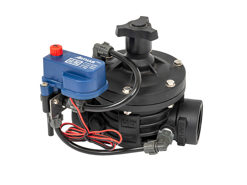
To build a resilient network, you must deploy the right tool for the right zone. Modern fluid regulation devices are engineered to handle specific hydraulic challenges, from aggressive pressure drops to complex digital scheduling.
Recognized as the undisputed backbone of agricultural water management, the diaphragm valve relies on a flexible, fabric-reinforced rubber seal to control flow. Because it features only one primary moving part, it is exceptionally rugged. This design is highly forgiving when handling dirty agricultural water pumped from rivers or ponds. There are no tight metal-on-metal sliding parts for sand or algae to jam. You will find these installed in nearly every mainline section, field lateral, and greenhouse manifold.
Topography and pump dynamics rarely provide a perfectly steady flow. A pressure reducing valve is specifically engineered to take a volatile, high upstream pressure and mechanically step it down to a constant, safe downstream pressure. If your field sits at the bottom of a steep hill, or if you are tapping into a high-pressure municipal line, this component is an absolute necessity. It is the primary safeguard for delicate drip emitter tapes and micro-sprinklers, ensuring they operate at their ideal 20 to 30 PSI range without blowing apart under stress.
To bring a network into the digital age, you need a translation layer between software and water. This is achieved by pairing a standard hydraulic body with an electromagnetic pilot coil. When an irrigation timer sends a 24V AC electrical impulse, the electromagnet activates, lifting a tiny plunger that vents the hydraulic control chamber.
For field applications requiring high durability, engineers often specify components like the AS50SC-T 2-inch T-type solenoid valve. Designed specifically for garden and agricultural environments, this model features a rugged glass-filled nylon body that resists harsh fertilizers. Its T-type configuration provides excellent flow dynamics with minimal head loss, making it a highly reliable bridge between raw hydraulic power and sophisticated electronic smart controllers.
While reducing devices protect downstream equipment, sustaining and relief models protect the upstream source. A pressure sustaining mechanism ensures that a mainline never drops below a critical threshold, preventing large centrifugal pumps from cavitating and destroying their impellers. Conversely, relief models act as emergency safety hatches. If a blockage causes pressure to spike dangerously high, the relief hatch instantly blasts open, venting the excess water safely into a drainage ditch before pipes can rupture.
| Valve Type | Primary Function | Ideal Application | Key Advantage |
|---|---|---|---|
| Diaphragm | Basic On/Off Flow Control | Mainlines, Laterals, Manifolds | High tolerance for sand and debris |
| Pressure Reducing | Lowers downstream pressure | Drip lines, Micro-sprinklers | Prevents thin-wall pipe blowouts |
| Solenoid Control | Electronic actuation | Automated smart farming zones | Seamless IoT and timer integration |
| Pressure Relief | Vents extreme pressure spikes | Pump stations, primary headers | Shields system from water hammer |
To truly master your field operations, you must understand the fluid mechanics happening beneath the cover. The secret lies in the pilot system. This is a delicate network of external tubing, micro-filters, and tiny orifices that dictate behavior by manipulating pressure differentials.
When the command is given to close the line, the pilot directs high-pressure water from the incoming mainline straight into the upper control chamber. Because the surface area of the top of the rubber seal is slightly larger than the surface area exposed to the water flowing underneath it, the downward hydraulic force overpowers the upward force. The seal is pushed firmly against the internal seat, halting the flow completely.
To open the line, the pilot cuts off the incoming pressure and opens an exhaust port. The trapped water in the upper chamber vents out into the atmosphere or downstream. Relieved of that crushing top weight, the incoming water pressure effortlessly lifts the seal off the seat. Flow resumes with a satisfying, deep mechanical whoosh.
Modulating models operate in a state of dynamic equilibrium. Instead of fully opening or slamming shut, the pilot constantly micro-adjusts the amount of water in the control chamber. It finds a perfect balance point, hovering the seal midway in the flow stream to create intentional friction, thereby regulating the exact pressure or volume passing through.
Selecting the correct components for an agricultural water distribution system requires a rigorous evaluation of technical parameters. Engineers and farm managers must move beyond basic pipe diameters and analyze the specific hydraulic conditions of their network. A mismatch between the specifications and the field conditions will inevitably lead to premature mechanical failure, water hammer, or inadequate crop hydration.
When evaluating an irrigation valve for commercial use, the decision-making process should be grounded in empirical data regarding flow dynamics, pressure ratings, fluid quality, and environmental exposure.
One of the most frequent engineering errors in system design is sizing the component strictly based on the existing pipe diameter. Sizing must be dictated by the anticipated flow rate, measured in Gallons Per Minute or Liters Per Hour, alongside the acceptable pressure loss through the body.
If a component is oversized for the actual flow, the internal seal will barely open. This causes the mechanism to operate too close to its seat, leading to a phenomenon known as chattering. This rapid vibration causes severe wear on the rubber parts and creates destructive hydraulic shockwaves. Conversely, an undersized unit forces water through a restricted orifice at high velocities. This results in excessive friction loss and potential cavitation that can erode the internal body.
Every hydraulic component operates within a specific pressure envelope. You must verify both the minimum pressure required to open the seal and the maximum pressure the housing can safely contain.
Because these devices utilize line pressure to operate, a minimum upstream pressure of roughly 10 to 15 PSI is required to lift the seal off the seat. If the system operates on a low-pressure gravity feed, standard field models may fail to open fully, causing severe flow restrictions. On the other end of the spectrum, high-pressure municipal connections or powerful centrifugal pumps require heavy-duty bodies with high burst-pressure ratings.
Agricultural water is rarely pristine. Ground water from wells often contains fine sand, while surface water from rivers or retention ponds carries organic debris, algae, and silt. The physical characteristics of your water source directly dictate the type of pilot system you should select.
While the main seal is highly tolerant of suspended solids, the pilot control circuits are highly susceptible to clogging. If you are pumping dirty water, specify models equipped with self-cleaning internal filters or external pilot filters. Ensure the rubber materials are constructed from reinforced natural rubber or specialized EPDM that resists degradation from agricultural chemicals, fertilizers, and suspended abrasives.
The material composition of the housing impacts its longevity, pressure tolerance, and resistance to environmental degradation. The choice generally comes down to engineered polymers versus traditional metals.
Glass-filled nylon is highly resistant to chemical corrosion and fertilizers. It is lightweight, cost-effective, and entirely immune to rust, making it the preferred choice for general field laterals and highly corrosive water sources. Cast iron or ductile iron offers exceptional structural integrity, capable of handling massive flow volumes and very high pressure ratings like PN16 or PN25. These are best suited for primary pump stations and large municipal-scale mainlines, though they require high-quality epoxy coatings to prevent internal rust.
Even the most robust flow controllers require periodic maintenance and occasional troubleshooting. Because these devices rely on fluid dynamics and pressure differentials, most operational failures can be traced back to hydraulic imbalances, debris blockages, or compromised seals. Understanding how to diagnose these issues systematically on the field will minimize downtime and prevent catastrophic crop loss.
When a manifold remains stuck in the open position, water continues to flood the zone regardless of controller commands. This is one of the most common and potentially damaging issues encountered by field technicians.
A zone that refuses to open deprives crops of vital hydration, posing an immediate threat to plant health during peak summer heat.
The agricultural sector is undergoing a rapid digital transformation, often referred to as Precision Agriculture. While the fundamental mechanical principles of fluid regulation remain unchanged, the methods used to command and monitor these devices are evolving dramatically.
Historically, networks were operated manually or via simple time-based mechanical clocks. Today, the integration of the solenoid control valve with the Internet of Things is creating highly responsive, data-driven watering systems. Modern smart controllers act as the central nervous system, connecting to local weather stations, satellite evapotranspiration data, and in-field soil moisture sensors. When sensors detect that soil moisture has dropped below a specific volumetric threshold, the controller sends an electrical impulse to the field node. The field node translates that digital command into a hydraulic action, opening the flow precisely when the crop needs it, and closing it the moment optimal saturation is reached.
Advanced Supervisory Control and Data Acquisition systems now utilize telemetry to monitor performance in real-time. By installing pressure transducers upstream and downstream, farm managers can view live pressure differentials on a smartphone dashboard. If a sudden pressure drop indicates a ruptured mainline, the system can instantly send a text alert and automatically trigger upstream emergency shut-off protocols to prevent flooding. This seamless integration of robust mechanics with intelligent digital oversight represents the future of water management.
Selecting the correct components ensures your distribution network succeeds from the primary pump station down to the furthest field lateral. Proper engineering choices protect expensive PVC pipes, drastically improve overall water efficiency, and guarantee that your crops receive uniform hydration. A truly reliable system relies heavily on highly accurate pressure management and dynamic flow control.
By investing in quality equipment and adhering to strict sizing guidelines, you drastically reduce long-term maintenance costs and shield your harvest from the devastating effects of uneven water distribution. Upgrade your network today. Explore the full range of robust, field-proven fluid regulation solutions at Arka Irrigation to secure your infrastructure and maximize your agricultural yields for seasons to come.
A basic hydraulic model operates strictly using the physical pressure of the water within the pipeline to open, close, or regulate flow. A solenoid model is simply a hydraulic unit that has been equipped with an electromagnetic component. This electromagnetic component acts as an electronic trigger. It receives an electrical signal from an irrigation controller and translates it into a hydraulic command, allowing the water pressure to physically move the internal seal.
No. Agricultural environments demand specialized equipment. Standard indoor plumbing fixtures, such as brass gate valves or basic ball valves, are designed for clean, filtered municipal water and relatively static flows. Agricultural models are engineered to handle massive volumes of water, severe pressure fluctuations, and significant amounts of abrasive debris like sand, silt, and algae. Using a standard plumbing fixture in a field environment will result in rapid clogging, seal failure, and potential structural bursting.
Sizing should never be based solely on your pipe diameter. First, calculate the total flow rate of your drip zone in Gallons Per Minute. Next, consult the manufacturer's friction loss chart. You want to select a size where the flow velocity remains between 3 to 7 feet per second, ensuring there is enough pressure drop to allow the internal seal to operate smoothly without causing destructive vibration or chattering.
The most frequent cause is debris trapped in the pilot system. If sand or algae clogs the tiny pilot tubes, high-pressure water cannot enter the upper control chamber to push the rubber seal down. Another common culprit is a torn internal rubber seal, which prevents pressure from building up in the chamber. Finally, check your manifold to ensure the manual bleed screw was not accidentally left in the open position after routine maintenance.
Drip components, such as emitter tapes and micro-tubing fittings, are engineered with thin walls designed for low-pressure operation. This is usually between 15 to 30 PSI. Standard agricultural mainlines and pump stations often operate at pressures exceeding 60 to 100 PSI to move water across long distances. If this high-pressure water enters a drip zone without being regulated, it will instantly blow the delicate fittings apart and rupture the drip lines. A pressure reducing device safely drops the incoming high pressure to a constant, low pressure suitable for micro-irrigation.


