
Views: 0 Author: Site Editor Publish Time: 2026-10-22 Origin: Site


Ever seen a main pipeline shatter because a pump tripped? I have. Pressure surges can instantly destroy expensive pipes and downstream machinery. Standard manual valves simply cannot react fast enough to these erratic hydraulic changes. Consequently, this lag leaves your entire downstream fluid system highly vulnerable to sudden ruptures and costly downtime. In this post, you will learn exactly how a remote control pressure reducing hydraulic valve solves this issue completely. It acts as an intelligent, active shield for your critical infrastructure.
Want to truly grasp system protection? You must first understand the architecture of these devices. They are hybrid mechanisms. A remote control pressure reducing valve elegantly combines fluid dynamics with electronic automation to regulate fluid energy in real-time.
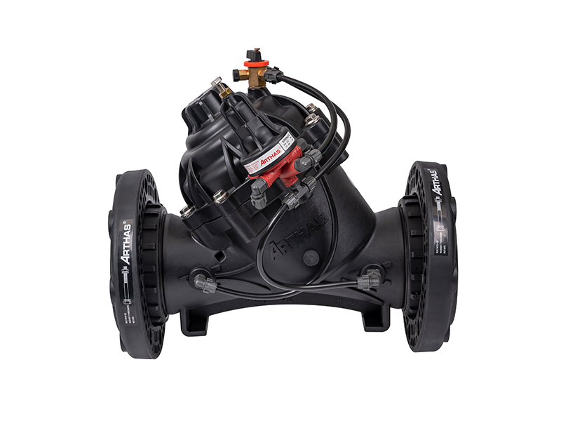
The base structure of this device is typically a piston-actuated main valve or a flexible diaphragm valve. The main body houses an elastomer diaphragm that divides the internal space into a control chamber and a flow passage. Ultimately, the vertical movement of this diaphragm dictates how much fluid can pass through the seat. This physical restriction throttles the pressure.
Attached to this main body is the pilot system. The pressure-reducing pilot is a smaller, highly sensitive mechanical valve acting as the brain of the operation. It continuously senses the downstream pressure through a dedicated sensing line. If the downstream pressure rises above the set limit, the pilot immediately adjusts the flow of water into the main valve control chamber. This action forces the diaphragm down to restrict the main flow and reduce the pressure.
Standard pilot systems are highly effective on their own. However, they require manual adjustment out in the field. Adding electronic actuators transforms a standard mechanical valve into a smart, networked device. By integrating an electronic coil into the pilot circuit, engineers can manipulate the valve set points digitally.
These actuators receive electrical signals from centralized control systems using various communication protocols. Consequently, operators can change pressure parameters, open or close the valve entirely, or set automated pressure schedules without ever stepping foot on the site.
Recent industry analyses highlight a massive shift in how facility managers approach fluid control. Aging municipal infrastructure and extreme weather events cause highly unpredictable supply fluctuations. Because of this, the industry is rapidly moving away from passive safety measures.
The integration of internet-connected smart water grids has made remote-controlled active pressure management an absolute necessity. Modern engineers deploy these automated valves not just for basic safety. They use them to gather real-time hydraulic data, optimize energy consumption, and proactively predict system stress before a critical failure occurs. Reducing background leakage through dynamic pressure modulation is now a top priority for water conservation globally.
Fluid networks are highly volatile environments. Minor changes in pump speeds, fluctuating tank levels, or sudden valve closures create severe hydraulic anomalies. Without proper and instantaneous regulation, these anomalies pose a severe threat to downstream infrastructure.
When fluid pressure exceeds the design limits of downstream equipment, the physical consequences are destructive. High steady-state pressure easily causes seals to blow out, filtration membranes to rupture, and delicate metering equipment to lose calibration.
Even more dangerous is the phenomenon known as hydraulic shock. When fluid is forced to stop or change direction suddenly, a massive shockwave travels backward through the piping system. This transient pressure spike can be exponentially higher than the standard operating pressure of the system. If a downstream valve closes too quickly, the resulting shockwave can literally tear pipe joints apart and destroy sensitive sprinkler heads.
The financial impact of unregulated pressure extends far beyond the mere cost of replacing a broken pipe. System downtime halts production in industrial plants, disrupts municipal water supplies, and damages delicate crops. Furthermore, undetected leaks caused by micro-ruptures lead to massive fluid loss over time. Implementing a highly responsive regulation system acts as a physical insurance policy for your entire network. By absorbing upstream fluctuations, the valve preserves structural integrity and prevents catastrophic financial losses.
Understanding the physics behind pressure regulation helps system operators make informed decisions regarding valve sizing and network placement. The entire process relies on creating a dynamic equilibrium between competing fluid forces.
The pressure reduction process begins as high-pressure fluid enters the inlet of the hydraulic control valve. A small portion of this fluid is routed through control tubing directly into the pilot circuit. The pilot valve is calibrated with a specific spring tension representing your desired downstream pressure.
When the downstream pressure is lower than the set point, the pilot valve opens up. This relieves fluid from the upper control chamber of the main valve. The incoming fluid pressure then pushes the diaphragm upward, permitting more flow. Conversely, if downstream pressure begins to exceed the set point, the pilot valve restricts its opening. This forces fluid to accumulate in the main control chamber, pushing the diaphragm downward. The flow path narrows, creating a physical pressure drop across the valve seat.
The true engineering value of this mechanism lies in its dynamic response. Upstream pressure in a pipeline is rarely static. It fluctuates constantly based on pump cycles and overall grid demand. However, the hydraulic pilot continuously modulates the diaphragm in real-time. Even if the upstream pressure wildly fluctuates from 100 to 150 PSI within seconds, the main valve continuously micro-adjusts its position. It keeps the downstream pressure perfectly stable at a safe 60 PSI. This guarantees sensitive downstream equipment receives a consistent flow of fluid at all times.
Mechanical pressure regulation is effective, but modern fluid management requires adaptability. Integrating remote control capabilities elevates the valve from a static safety device to an active network management tool.
By utilizing a solenoid control valve within the pilot architecture, operators gain unparalleled command over system dynamics. In a centralized control room, engineers monitor live pressure data from downstream sensors. If demand changes, the central computer sends an electrical pulse to the solenoid.
Specifically, the solenoid adjusts the hydraulic pilot to change the pressure set-point instantly. This enables sophisticated time-based pressure management. For instance, a municipality can lower the system pressure at night when demand is historically low. This significantly reduces background leakage and conserves water, before automatically raising the pressure again just before morning peak hours begin.
Beyond standard regulation, remote integration provides critical fail-safe mechanisms. Imagine a catastrophic event occurs downstream, such as a major pipe rupture caused by construction equipment. Flow sensors will immediately detect a massive drop in resistance. The central control system can instantly command the solenoid to initiate an emergency override.
The solenoid redirects full upstream pressure directly into the main control chamber. This forces the valve to close completely and lock shut in a matter of seconds. This immediate isolation prevents severe flooding, environmental contamination, and excessive fluid loss.
When designing a fluid management system, engineers must differentiate between pressure regulation and pressure relief. While both mechanisms deal with managing excessive force within a pipeline, their operational logic and primary functions differ significantly. Understanding these distinctions is critical for implementing an effective safety strategy.
A pressure reducing valve is designed to provide continuous, active modulation. Installed directly in-line with the primary flow, its main objective is to take a high, fluctuating upstream pressure and reduce it to a steady downstream pressure. Regardless of how erratically the supply pressure changes, it restricts the flow area dynamically. It operates constantly during normal system functionality.
In contrast, a pressure relief valve serves strictly as an emergency venting mechanism. These valves are typically installed on a branch or a tee off the main pipeline. Under normal operating conditions, a relief valve remains completely closed. It only actuates when the system pressure spikes above a pre-determined critical safety threshold. When this occurs, the valve opens rapidly to divert the excess fluid out of the system, preventing immediate pipe rupture.
| Feature | Pressure Reducing Valve | Pressure Relief Valve |
|---|---|---|
| Primary Function | Maintains steady downstream pressure | Vents extreme pressure spikes |
| Installation Location | In-line on the main pipeline | Branch or Tee connection |
| Operating State | Continuously modulating | Normally closed for emergencies |
| Fluid Action | Throttles fluid to reduce energy | Discharges fluid out of the system |
| System Role | Operational regulation | Emergency fail-safe |
The integration of remote control capabilities into fluid regulation has transformed how various industries manage their infrastructure. By allowing centralized control over distributed networks, these smart valves mitigate risks across diverse applications.
In modern agriculture, maintaining precise water delivery is paramount for crop yield and equipment longevity. Imagine a sprawling vineyard situated on a steep hillside. Topography changes naturally create severe pressure differentials as water flows downhill. If high pressure reaches delicate micro-drip lines, it causes immediate blowouts. Utilizing an advanced irrigation valve equipped with remote pressure reducing capabilities allows farm managers to adjust flow dynamics based on real-time soil moisture data. This ensures the exact required pressure is delivered to every zone.
Municipal water grids are highly complex networks. They must balance high-pressure transmission mains with low-pressure residential plumbing. If high pressure from a main line transfers directly into a residential grid, it destroys water meters and ruptures domestic pipes. To combat this, municipalities deploy remote control hydraulic valves at critical district metering areas. Operators monitor network demand and adjust the pressure set-points dynamically to reduce background leakage.
Industrial environments deal with highly volatile fluids and extreme operational demands. Downstream equipment often includes sensitive heat exchangers and precise chemical dosing machinery. A sudden pressure surge can compromise the structural integrity of a boiler. Implementing a smart control valve ensures these critical assets receive fluid at a strict, continuous pressure.
Selecting the correct valve for a specific application requires a rigorous engineering approach. Choosing a valve based solely on the existing pipe diameter is a frequent and costly error. It always leads to premature mechanical failure and erratic system behavior.
The most critical parameters in valve selection are the minimum and maximum flow rates, alongside the required pressure differential. When calculating the Flow Coefficient, always account for the absolute maximum flow during peak demand.
The physical construction of the valve must be fully compatible with the fluid being transported. For example, municipal water applications often use cast iron for its high tensile strength. However, agricultural and corrosive environments demand different solutions.
Take the AS110PR Arthas 4-inch pressure reducing valve as a prime field example. Engineered for drip irrigation systems, it utilizes a heavy-duty glass-filled nylon body. This specific material choice provides exceptional resistance to liquid fertilizers and harsh outdoor weathering while maintaining a high flow capacity with minimal head loss. The core of any reliable unit is its flexible elastomer. The longevity of the entire unit depends entirely on the diaphragm flexing millions of times without tearing.
When integrating a solenoid for remote operation, deciding on the fail-state configuration is a critical safety consideration. You must determine what should happen if the facility loses electrical power.
While remote control pressure reducing valves are engineered for rugged durability, they operate in harsh environments. Establishing a proactive maintenance protocol is essential to prevent unexpected downtime.
System operators should implement a scheduled inspection routine focusing heavily on the external control loop. A poorly maintained pilot system will invariably cause the main valve to fail.
One of the most destructive phenomena in fluid dynamics is cavitation. It occurs when the pressure drop across the valve is so extreme that the fluid static pressure falls below its vapor pressure. This causes temporary vapor bubbles to form. As the fluid recovers pressure upon exiting the valve, these bubbles collapse violently.
Cavitation is easily identifiable by its distinct sound. It often sounds as though gravel is flowing rapidly through metal pipes. Over time, these micro-implosions pit and erode the solid valve body and internal trim, leading to catastrophic failure. Practical solutions include installing two valves in series to stage the pressure drop gradually, or retrofitting the existing valve with a specialized anti-cavitation trim.
A remote control pressure reducing hydraulic valve is far more than a simple pipe fitting. It is an active, intelligent defender of your vital downstream infrastructure. By automatically absorbing pressure surges and allowing for real-time remote adjustments, it protects your network from severe structural damage.
Ultimately, the upfront costs of installing a smart, automated valve are minor compared to the astronomical expense of replacing ruptured downstream equipment, cleaning up environmental spills, or dealing with prolonged facility downtime. Stop catastrophic system failures before they happen. Evaluate your specific flow parameters and upgrade your fluid management system today by exploring the high-performance hydraulic control solutions available at Arka Irrigation.
Yes, many standard hydraulic valves can be easily retrofitted with a solenoid control valve and a modified pilot circuit. This upgrade allows you to enable remote operation without needing to remove or replace the entire heavy valve body from the pipeline. A technician simply adds the electronic actuator to the existing hydraulic control loop, connecting it to your central PLC or SCADA system for immediate automated control.
The behavior of the valve during a power failure depends entirely on the solenoid configuration you select during installation. You can choose a latching solenoid, a normally open setup, or a normally closed setup. This choice ensures the valve defaults to a safe position based on the specific safety requirements of your downstream equipment.
A diaphragm valve is preferred because it features very few moving mechanical parts, which significantly reduces the risk of friction-induced wear and mechanical binding. The flexible elastomer diaphragm offers excellent, immediate sensitivity to minor pressure changes in the pilot line. Furthermore, it provides a tight, drip-free seal when fully closed, making it highly reliable for continuous modulation.
The hydraulic pilot mechanism reacts almost instantly to physical pressure changes occurring within the pipeline. Meanwhile, remote electronic commands sent via the control room are executed as fast as your specific network latency allows. This powerful combination of instantaneous hydraulic reaction and high-speed electronic oversight ensures real-time protection.
For optimal performance, install the valve in a straight section of the pipeline, away from turbulent flow areas caused by elbows or pumps. Upstream and downstream isolation valves should be installed to facilitate maintenance. Additionally, ensure the electronic solenoid is positioned in an area accessible for wiring and protected from complete submersion unless rated for underwater use.
If your system requires a massive pressure reduction ratio, a single standard valve will likely cavitate. To prevent this, engineers recommend staging the pressure drop by installing two pressure reducing valves in series. Alternatively, you can specify a valve equipped with specialized anti-cavitation cages that safely dissipate the kinetic energy of the fluid before it damages the valve body.


