
Views: 0 Author: Site Editor Publish Time: 2026-10-23 Origin: Site


Unregulated fluid pressure destroys pipelines and wastes millions of gallons of water daily. In massive agricultural, municipal, and industrial systems, taming this immense hydraulic force is a critical engineering challenge. Facility managers and field engineers constantly battle pressure surges to prevent catastrophic pipeline failures. They rely heavily on the cast iron diaphragm hydraulic water controlling valve to safeguard these networks.
This technical guide breaks down exactly how this vital mechanical equipment operates. By exploring its core components, fluid dynamics, and field-tested configurations, you will gain a practical understanding of how to specify and maintain these units for decades of reliable service.
In massive fluid management networks, maintaining consistent flow parameters despite fluctuating consumer demand is a highly complex task. A pilot-operated diaphragm valve is a specialized mechanical device designed to regulate these parameters automatically. Unlike traditional motorized gate or butterfly valves that require massive electrical actuators to turn heavy gears, this specific classification of equipment uses the kinetic and potential energy of the flowing water to actuate its own internal mechanisms.
The choice of cast iron—frequently upgraded to ductile iron like EN-GJS-400-15 in modern manufacturing—is a deliberate engineering decision. Cast iron provides the sheer mechanical mass and structural integrity necessary to withstand significant hydrostatic testing pressures. These are often rated at PN10, PN16, or PN25 bar. Furthermore, ductile iron is highly resistant to mechanical wear, offers excellent vibration dampening properties, and remains highly cost-effective for large-diameter pipeline requirements ranging from DN50 up to massive DN1000 mains.
At the heart of this heavy-duty exterior lies the elastomer diaphragm. This flexible membrane acts as the sole moving component within the main chamber. It is typically manufactured from nylon-reinforced synthetic rubber such as ethylene propylene diene monomer or nitrile butadiene rubber. The rubber creates a dynamic barrier that separates the upper control zone from the primary fluid passage, translating subtle hydraulic pressure changes into powerful mechanical movement.
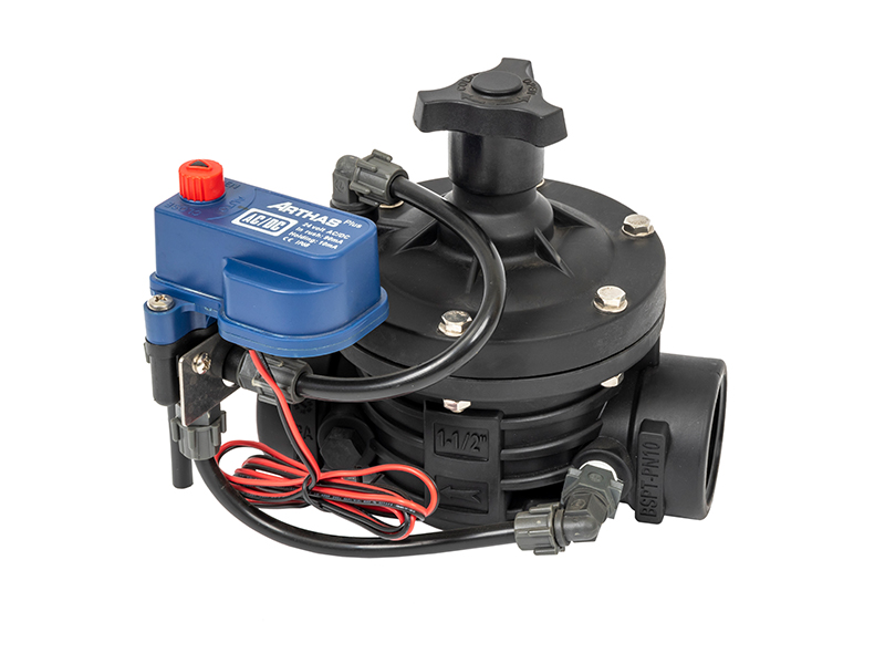
To fully comprehend how this equipment manages complex fluid dynamics, we must look beneath the heavy iron cover. The long-term reliability of the unit stems entirely from the seamless synergy of its internal and external components.
Serving as the primary pressure vessel, the main body is engineered using advanced computational fluid dynamics. The internal geometry is typically cast in a sweeping Y-pattern or a traditional Globe-pattern. This specific hydrodynamic design is crucial for field performance. It minimizes internal turbulence, drastically reduces pressure head loss, and prevents cavitation. Cavitation is the violent formation and collapse of vapor bubbles that can literally chew through solid metal over time.
Secured tightly between the lower body and the top cover, the diaphragm is the dynamic muscle of the operation. Embedded within the rubber is a layer of industrial-grade nylon fabric, which prevents the elastomer from tearing under extreme pressure differentials. Situated directly above this membrane is a heavy-duty compression spring, usually forged from 304 or 316 stainless steel. This spring provides the initial mechanical force required to push the valve into a closed position when the pipeline is depressurized or drained.
Located directly above the diaphragm and completely enclosed by the cast iron top cover, the control chamber is the primary actuation zone. The exact volume of water present in this enclosed space dictates the physical position of the diaphragm. When water is forced into this chamber, pressure builds rapidly, pushing the rubber down. Conversely, when water is vented out, the internal pressure decreases, allowing the membrane to rise.
If the main iron body is the muscle, the external pilot system is undeniably the brain. Consisting of miniature control regulators, Y-strainers, needle restrictors, and interconnected tubing, the pilot system continuously senses upstream or downstream conditions. The tubing is often crafted from copper, reinforced plastic, or stainless steel. It automatically directs fluid into or out of the control chamber to achieve the precise diaphragm position required by the operator.
The operation of this equipment is governed by the fundamental principles of fluid mechanics. Specifically, it relies on the relationship between pressure, surface area, and force. By continuously altering the volume of trapped fluid in the upper control chamber, the mechanism modulates the main pipeline flow.
Imagine a scenario where a reservoir is full, and the inflow needs to stop immediately. To close the unit, the pilot circuit directs high-pressure fluid from the upstream side of the pipeline directly into the upper control chamber. Although the water pressure inside this chamber is nearly identical to the upstream line pressure, the structural design ensures that the surface area on the top of the diaphragm is significantly larger than the area exposed to the water on the bottom. Because force equals pressure multiplied by area, the downward hydraulic force generated in the upper chamber easily overcomes the upward force of the flowing main line. This differential pushes the diaphragm firmly against the metal seat, creating an impenetrable drip-tight seal.
When system parameters demand fluid delivery, the pilot system shifts its configuration. It blocks the inflow of high-pressure upstream water and simultaneously vents the trapped water from the control chamber downstream or out to the atmosphere. As the pressure above the diaphragm plummets, the high-pressure fluid rushing through the main pipeline exerts a massive upward force against the bottom of the rubber membrane. Overcoming the tension of the stainless steel spring, the diaphragm lifts smoothly away from the seat, allowing unrestricted passage.
In most real-world industrial and municipal scenarios, these devices do not simply slam open or shut. They must carefully regulate flow. To achieve this delicate balance, a hydraulic control valve acts as a proportional controller. The pilot continuously adjusts the micro-flow of fluid entering and exiting the upper chamber. By balancing these minute hydraulic changes, the pilot creates a state of equilibrium. The diaphragm hovers precisely at an intermediate mid-stroke position, restricting the flow passage just enough to maintain a highly accurate pre-set pressure rate downstream.
One of the most significant engineering advantages of this architecture is its absolute modularity. The heavy cast iron base and internal membrane remain identical across different applications. Only the external pilot circuitry changes to alter the primary function.
The most prevalent configuration in civil engineering is the pressure reducing valve. In systems where the source pressure is dangerously high for downstream residential plumbing to handle safely, this setup is deployed. The pilot continuously monitors the downstream pressure zone. If it detects a rise above the safe set-point, it allows more fluid into the control chamber, pushing the diaphragm down to restrict the passage. It guarantees a steady, safe lower pressure regardless of wild upstream fluctuations.
When modern automation is required, engineers integrate an electrical actuator into the hydraulic circuit, transforming the unit into a solenoid control valve. The solenoid receives low-voltage electrical signals from remote timers, programmable logic controllers, or centralized computer networks. When energized, the solenoid snaps open or closed, which in turn actuates the main hydraulic diaphragm. For instance, integrating a 2-inch T-type solenoid configuration like the AS50SC-T series allows for operating pressures ranging from 0.3 to 10 bar. This specific setup bridges the gap between raw mechanical power and precise digital control, delivering rapid response times for automated watering blocks.
A pressure sustaining configuration performs the exact opposite function of a reducing regulator by monitoring upstream pressure. If the source pressure drops below a critical threshold, the pilot forces the main body to close. This prevents the system from draining completely and protects expensive upstream pumps from running dry. Alternatively, when configured as a relief valve, the unit remains tightly closed under normal conditions. It opens in a fraction of a second to discharge fluid if a sudden destructive pressure spike, also known as water hammer, occurs.
Engineers often debate whether to specify a diaphragm or a piston mechanism for large-scale projects. The following breakdown highlights why diaphragm technology is frequently the superior choice for raw water applications.
| Feature | Cast Iron Diaphragm Valve | Traditional Piston Valve |
|---|---|---|
| Moving Parts | Only one flexible rubber membrane. No friction. | Multiple sliding metal components. High friction. |
| Debris Tolerance | Excellent. Rubber seals around sand and grit easily. | Poor. Grit scores the metal cylinder, causing jams. |
| Maintenance Speed | Fast top-entry access. Repaired in-line in minutes. | Requires heavy lifting to remove the entire body. |
| Response Time | Highly responsive to micro-pressure changes. | Slower due to mechanical inertia and metal friction. |
Because they are entirely self-actuating and incredibly resilient, these mechanisms are deployed in some of the most demanding environmental conditions globally.
Picture a sprawling 1000-acre almond orchard with undulating hills and varying elevations. Managing water distribution across this terrain is a logistical nightmare without proper regulation. Here, the unit functions as an indispensable irrigation valve. It separates massive watering blocks, protects delicate low-pressure drip tape from bursting, and ensures that every single tree receives an identical volume of water regardless of its elevation. Paired with solenoids, it allows farm managers to execute complex watering schedules directly from a smartphone.
City water grids are notoriously complex, dealing with constant unpredictable variations in consumer demand. Municipal engineers utilize these devices to carve cities into distinct pressure management areas. By installing reducing configurations at the inlet of these residential zones, operators can artificially lower the background pressure during low-demand night hours. This targeted pressure drop drastically reduces the volume of water lost through microscopic leaks in aging underground pipes.
Within heavy industrial settings like deep-shaft mining operations, steel foundries, and chemical processing plants, fluid is moved in massive volumes for cooling, washing, and slurry transport. Cast iron diaphragm units are utilized to control water levels in massive cooling tower basins. They also manage abrasive slurry flow and serve as instant-response deluge valves in heavy-duty fire protection systems where absolute reliability is a matter of life and safety.
The global water management industry is currently undergoing a massive digital transformation. Historically, infrastructure relied purely on reactive mechanical systems. However, driven by severe global water scarcity and the urgent financial need to reduce non-revenue water, municipalities and industrial facilities are upgrading their networks. They are increasingly blending traditional cast iron durability with advanced Internet of Things technology.
The current engineering trend is moving rapidly toward predictive analytics and smart water grids. While the robust iron body and elastomer diaphragm remain the physical standard due to their unmatched reliability, the external pilot systems are becoming highly digitized. Modern pilot circuits are frequently retrofitted with smart pressure transducers and wireless telemetry modules. This allows operators to monitor micro-fluctuations in flow and pressure in real-time. Instead of sending technicians into the field to manually turn pilot screws, facility managers now adjust set-points remotely based on artificial intelligence demand forecasts. This seamless fusion of heavy metal mechanics and smart data represents the definitive future of sustainable fluid infrastructure.
When specifying infrastructure components expected to last upwards of 30 to 50 years, purchasing managers must look beyond the initial price tag and evaluate the total cost of ownership.
Even the most precisely engineered fluid management systems will experience premature wear or erratic regulation if fundamental installation guidelines are ignored. Adhering to strict field protocols ensures operational longevity.
Before introducing any hydraulic equipment into a pipeline network, thoroughly flushing the main line is mandatory. During construction, debris such as welding slag, rocks, and PVC shavings frequently accumulate inside the pipes. If not flushed, this debris will travel downstream, potentially lodging under the elastomer membrane or clogging the sensitive pilot tubing.
Regarding orientation, horizontal installation with the valve cover facing upward is universally recommended. While smaller configurations can tolerate vertical alignment, horizontal placement ensures that the internal spring and diaphragm operate symmetrically without uneven gravitational wear. Additionally, installing manual isolation valves upstream and downstream allows technicians to depressurize the main body for safe inspection without draining the entire municipal grid.
Because these units operate using line fluid, routine maintenance focuses primarily on the pilot system. The external circuit typically includes a miniature Y-strainer designed to protect the pilot regulators from particulate matter. This strainer must be blown down and cleaned periodically. If it clogs, the control chamber cannot vent or fill properly, causing the main body to become completely unresponsive.
One of the greatest maintenance advantages is the top-entry design. When internal components require replacement, the heavy cast iron body does not need to be unbolted from the pipeline flanges. Technicians simply remove the upper cover bolts, lift the bonnet, and access all moving parts directly in-line, drastically reducing facility downtime.
For system engineers, selecting the appropriate equipment involves far more than matching the flange diameter to the existing pipe. Specifying the wrong unit can lead to severe hydrodynamic issues, including destructive water hammer.
A common yet costly error is sizing the unit strictly based on the nominal diameter of the pipeline. Control regulators must be sized based on the actual anticipated flow rate in cubic meters per hour and the acceptable pressure drop. If a unit is oversized, the diaphragm will operate too close to the closed position. This creates a high-velocity restriction that causes rapid violent oscillation, destroying the rubber. Conversely, an undersized unit forces fluid through at extreme velocities, resulting in massive pressure loss and potential cavitation. Always consult the manufacturer flow coefficient ratings before purchasing.
Furthermore, the structural integrity of the iron body must exceed the maximum potential pressure of the network, including transient surges. Bodies are categorized by nominal pressure ratings. PN10 or 145 PSI is generally suitable for low-pressure agricultural networks. PN16 or 232 PSI is the standard for municipal grids. For high-rise buildings or deep mining, PN25 ductile iron is heavily recommended.
Finally, clearly define the primary objective before selecting the pilot system. If the goal is purely mechanical downstream protection, a standard PRV pilot is sufficient. If the facility requires integration with a centralized computer network for timed batching, specifying a solenoid-equipped pilot with the correct voltage requirements is mandatory.
The brilliant yet elegantly simple design of the cast iron diaphragm hydraulic water controlling valve makes it an indispensable tool for managing complex fluid networks safely and efficiently. By leveraging the natural power of water pressure, it provides highly accurate regulation without the need for massive external power grids.
Whether you are protecting residential plumbing from municipal pressure spikes or automating a massive agricultural operation, choosing high-quality, properly sized cast iron equipment guarantees excellent long-term return on investment and system stability.
Ready to upgrade your fluid management infrastructure? Explore the robust catalog of professional-grade solutions at Arka Irrigation. Contact our dedicated sales engineering team to match the exact specifications required for your project, and request a custom quote to ensure your next installation operates flawlessly.
The primary distinction lies in the internal moving mechanism and its tolerance to fluid impurities. Diaphragm styles utilize a flexible elastomer membrane to regulate flow. Because there are no sliding metal-on-metal parts, they are highly resistant to debris, sand, and minor particulates. In contrast, a piston valve uses a rigid cylindrical piston sliding within a metal chamber, which can easily jam or score if the water contains grit.
Yes, absolutely. The fundamental operating principle relies entirely on the hydraulic energy provided by the existing pipeline pressure. Standard configurations use pilot tubes to direct line pressure into the control chamber to modulate the diaphragm mechanically. Electricity is only introduced if the system design specifically requires remote digital automation via solenoids.
The lifespan of the elastomer membrane varies based on operational parameters such as water chemistry, operating pressure, and cycle frequency. Under standard clean-water conditions with stable pressures, a high-quality rubber diaphragm can last between 3 to 7 years. It is standard engineering practice to conduct a visual inspection annually to check for micro-tears or loss of elasticity.
Yes, provided the unit has been properly treated. Bare iron is susceptible to oxidation. To make it safe and compliant for potable water networks, the body must be internally and externally coated with a non-toxic fusion-bonded epoxy. This coating must carry relevant international certifications preventing any metal leaching and inhibiting bacterial growth.
A failure to achieve a drip-tight seal is typically caused by one of three issues. First, the pilot tubing or the Y-strainer may be clogged with debris, preventing line pressure from entering the upper chamber. Second, a physical obstruction like a small rock may be trapped between the rubber and the metal seat. Third, the elastomer itself may have ruptured, preventing pressure from building up to overcome the upstream flow.
Proper sizing requires calculating the continuous flow rate, the maximum peak flow, and the minimum flow demand of your system. You should never size the valve based solely on the pipeline diameter. Instead, use the flow coefficient data provided by the manufacturer to select a valve size where the diaphragm operates efficiently in the mid-stroke position during normal flow conditions.
Water hammer in these units is usually caused by the valve closing too quickly. This rapid deceleration of fluid creates a destructive shockwave. To resolve this, field technicians adjust the needle valve restrictor on the pilot circuit to slow down the rate at which water fills the upper control chamber, thereby extending the closing time and softening the shut-off process.


