
Views: 0 Author: Site Editor Publish Time: 2026-10-23 Origin: Site


Are clogged filters causing costly system downtime? For many facility managers and agricultural engineers, manual cleaning wastes both time and precious water resources. When an irrigation network or an industrial cooling loop shuts down for maintenance, the financial losses accumulate rapidly.
An advanced filtration solution solves this exact bottleneck. By utilizing a highly engineered matrix, this technology provides continuous water filtration without ever stopping your main flow. In this comprehensive guide, you will learn exactly how these systems trap debris efficiently, the mechanics behind their uninterrupted self-cleaning cycles, and why they are rapidly replacing traditional media filters in modern pump houses.
Maintaining consistent water quality is a strict operational requirement across heavy industry and precision agriculture. A highly efficient disc filter system is an engineered unit designed to capture suspended solids, sticky organic matter, and inorganic debris from raw water sources. Unlike traditional sand media beds or flat wire mesh screens, this equipment relies on a precise, three-dimensional matrix to purify water.
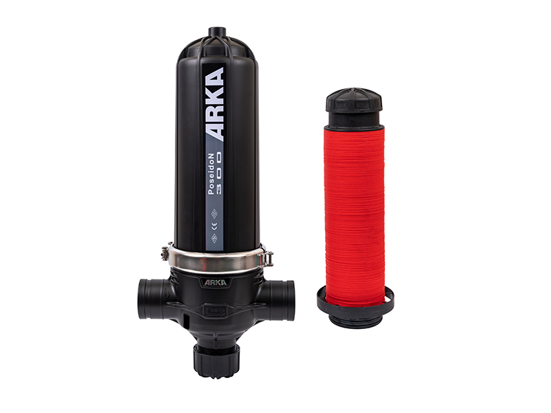
The core of the system consists of hundreds of synthetic, color-coded rings. Engineers commonly refer to these as discs. Manufacturers mold these components from durable, corrosion-resistant polymers like industrial-grade polypropylene or polyamide. Each individual disc features microscopic, diagonal grooves etched into both sides. When stacked on a central spine and tightly compressed by hydraulic pressure, these intersecting grooves create a complex network of internal passageways.
Specifically, this matrix forces water through a tortuous, multi-directional path. It effectively traps particles of highly specific sizes before they can reach delicate downstream equipment. Built for heavy-duty rigors, commercial units typically handle maximum operating pressures up to 10 bar, ensuring they survive demanding pump station environments.
To fully grasp the operational efficiency of this equipment, you need to examine its primary mechanical components. A standard industrial or agricultural setup is built from the following parts:
During standard operation, the system operates on an outside-in trajectory. Raw water enters the filter housing from the inlet manifold and completely surrounds the external surface of the disc stack.
Because the central piston applies high pressure to compress the discs together, the incoming water cannot simply bypass the filter. Instead, it is forced to travel through the microscopic intersections of the grooves to reach the hollow center of the spine. As the fluid navigates this complex maze, debris is securely captured within the grooves. The resulting clean water then flows out through the central spine and into the outlet manifold. Furthermore, the exact micron rating of the filter is determined entirely by the depth and width of the grooves manufactured into the discs.
The most significant engineering advantage of this technology is its utilization of 3D depth filtration. Understanding the distinction between depth and surface filtration is critical for facility operators when selecting equipment for biologically active water sources.
| Feature | Surface Filtration like 2D Screens | Depth Filtration like 3D Disc Stacks |
|---|---|---|
| Mechanism | Traps debris on a single, flat outer layer. | Traps debris throughout the entire depth of the filter matrix. |
| Organic Matter | Tends to smear, extrude, and blind the mesh quickly. | Effectively captures soft, stringy organics within the complex grooves without immediate blinding. |
| Holding Capacity | Lower capacity requiring more frequent cleaning cycles. | High capacity storing significantly more debris before a pressure drop occurs. |
| Filtration Path | Direct, straight-through path. | Tortuous, multi-directional path. |
Because debris is trapped throughout the entire volume of the disc stack rather than just on the outer edge, these filters are remarkably effective in environments facing heavy biological loading or fluctuating seasonal water quality.
To simplify field maintenance, manufacturers utilize a standardized color-coding system. This visual cue allows operators to identify the filtration grade immediately without consulting a manual. By simply swapping the internal disc stack, a maintenance technician can completely alter the filtration grade of the entire system without replacing the heavy external housings.
The most frequent question regarding this technology is how it manages to clean itself without halting the main water supply. The answer lies entirely in the modular architecture of the equipment. A continuous-flow system is rarely deployed as a single, isolated housing.
Instead, engineers design it as a multi-pod array. Multiple filter housings are installed in parallel, all connected to the exact same inlet, outlet, and drainage manifolds. This brilliant redundancy is what makes an automatic backwash filter so valuable for continuous processing plants.
When the system detects that it is time to purge accumulated debris, it does not shut down the entire array. The automated controller initiates a highly synchronized, staggered cleaning sequence.
The control valve on the first pod shifts, physically isolating that specific housing from the raw water inlet. Meanwhile, the remaining pods in the manifold continue to operate normally. They filter raw water and supply the downstream process without a single drop in pressure. A small percentage of the clean, filtered water produced by the active pods is redirected backward into the isolated pod to facilitate the cleaning process. Once the first pod is fully cleaned and flushed, it returns to the filtration phase. The controller then moves to clean the next pod in the sequence, ensuring zero operational downtime.
The self-cleaning cycle is a marvel of fluid dynamics. It relies on centrifugal force to clear trapped debris rapidly. Here is the exact mechanical breakdown of what happens inside the pod during those crucial seconds.
The entire process begins with a Differential Pressure switch. This sensor acts as the brain of the operation. It continuously monitors the hydraulic pressure at two distinct points: the inlet manifold before the filter, and the outlet manifold after the filter.
As the disc stack traps debris, the flow of water naturally becomes restricted. This causes the pressure on the outlet side to drop. When the difference in pressure between the inlet and outlet reaches a pre-calibrated threshold, typically between 0.5 and 0.7 bar, the switch sends an electrical signal to the system controller. This instantly triggers the backwash cycle.
Upon receiving the signal, the controller activates the 3-way valve on the first pod in the cleaning sequence. This valve simultaneously closes the raw water inlet to that pod and opens a pathway directly to the atmospheric drain.
Because the drain is at atmospheric pressure, the internal hydraulic pressure holding the disc stack together is immediately released. The central piston retracts slightly. This vital movement allows the tightly compressed stack of discs to decompress, loosen, and separate slightly from one another.
With the discs now loose, clean filtered water from the other active pods is forced into the isolated pod in an inside-out direction. The water enters the hollow central spine.
This spine is equipped with specially designed directional nozzles. As the high-pressure water exits these nozzles, it sprays tangentially against the inner edges of the loosened discs. This creates a powerful centrifugal effect, causing the individual discs to spin rapidly. The combination of the high-velocity water jets and the centrifugal spinning force violently ejects the trapped organic and inorganic debris out of the grooves. A minimum backwash pressure of 2.5 bar is generally required to spin the discs effectively. The dirty flush water is then expelled from the housing through the open drain port. Remarkably, this highly energetic process takes only 10 to 20 seconds per pod before returning to normal filtration.
When engineering a water treatment facility or an expansive irrigation network, decision-makers frequently face a critical choice. They must specify a disc filter or a self cleaning screen filter. While both are automated technologies designed to remove suspended solids, their internal mechanics and optimal use cases differ significantly.
A screen filter relies purely on surface filtration. Water passes through a two-dimensional stainless steel or synthetic mesh. When debris accumulates on the inner surface, a pressure switch triggers the cleaning cycle. Typically, a motor-driven suction scanner or a series of rotating brushes sweeps across the screen surface, vacuuming or scrubbing the accumulated particles away.
In contrast, the fundamental difference in geometry dictates their performance against different types of debris. Screen filters are highly effective at capturing hard, inorganic materials like sand, gravel, and pipe scale. However, when confronted with soft, organic matter like algae or sticky biological floc, the pressure of the water can extrude these pliable particles right through the flat mesh. Worse, the cleaning brushes can smear organics across the screen, causing a stubborn condition known as blinding.
Selecting the appropriate technology requires a thorough analysis of your source water profile. A disc setup is the undisputed winner in scenarios where the water source carries a high biological or organic load.
For example, agricultural operations drawing irrigation water from open canals or retention ponds frequently struggle with seasonal algae blooms. A screen filter in this environment would likely experience rapid blinding. A disc system traps the algae safely within its deep grooves and easily ejects it during the decompression and spinning phase. Similarly, in industrial applications like cooling tower make-up water, airborne organics are constant threats that depth filtration handles effortlessly.
Recent engineering analyses highlight a massive global shift toward sustainable, low-footprint water management. As water scarcity tightens environmental regulations globally, industrial facilities and large-scale agricultural operations are actively moving away from traditional sand media filters.
Sand filters require massive volumes of water to properly fluidize the bed and flush debris. They often run backwash cycles for several minutes at a time. The current industry trend strongly favors modular, continuous-flow technologies that maximize operational uptime while drastically minimizing the volume of wastewater sent to the drain. Furthermore, corporate ESG goals are pushing facility managers to adopt equipment that reduces energy consumption. This push for eco-efficiency is a primary driver behind the rapid adoption of highly efficient centrifugal disc technologies across municipal and commercial sectors.
Selecting the right equipment is not a guessing game. It requires matching your peak flow rates and water quality to the correct manifold configuration. Instead of buying a massive single unit, engineers build arrays based on modular pod capacities.
If your pump station delivers 50 cubic meters per hour, you might select a system utilizing three 2-inch pods. If your industrial cooling loop demands 400 cubic meters per hour, you would scale up to an array featuring eight or ten 3-inch or 4-inch pods. Always factor in a 15 to 20 percent safety margin on your flow rate to accommodate the water temporarily diverted during a backwash cycle.
Investing in an automated filtration array provides immediate operational advantages. For facility managers, the return on investment is calculated not just in equipment longevity, but in the drastic reduction of system downtime and manual labor.
The versatility of the depth filtration matrix allows it to be deployed across a wide spectrum of demanding environments. By providing precise micron-level filtration without flow interruption, these systems protect critical downstream infrastructure.
Modern farming heavily relies on precision water delivery systems. Micro-sprinklers and pressure-compensating drip emitters feature microscopic flow paths that are highly susceptible to clogging. Even a minor accumulation of organic biofilm can alter the flow rate, leading to uneven crop hydration. By installing automated filtration at the pump station, farmers ensure that organic matter from open water sources is completely intercepted.
In the industrial sector, water is a critical utility. Disc systems are frequently deployed as robust pre-filtration units for Reverse Osmosis and Ultrafiltration plants. RO membranes are highly sensitive. If organic matter reaches them, it causes severe fouling. Additionally, in cooling tower applications, these filters continuously remove airborne dust and biological growth from the cooling loop, maintaining optimal thermal transfer efficiency.
While the technology is inherently self-cleaning, establishing a proactive maintenance protocol is essential to ensure long-term performance. Ignoring routine checks can lead to inefficient backwashing and eventual flow restriction. Picture standing in a pump house. You want to hear the crisp, synchronized clicking of valves, not the sluggish groan of a clogged manifold.
To maintain peak efficiency, operators should integrate practical checks into their preventative maintenance schedules. First, check the differential pressure switch calibration. Periodically verify the hydraulic command tubes connecting the switch to the manifolds. Ensure they are free of air bubbles or micro-leaks, and confirm that the switch triggers accurately at the set threshold.
Second, conduct an annual inspection for mineral scaling. While discs handle organics flawlessly, hard water with high concentrations of calcium or magnesium can cause mineral scaling over time. Once a year, remove the disc stacks for a visual inspection. If calcification is present, soak the discs in a mild acid bath using a diluted hydrochloric or phosphoric acid solution. This dissolves the scale and restores them to factory condition without damaging the plastic.
Finally, ensure that the kinetic air release valves located at the highest points of the manifolds are functioning correctly. Trapped air in the system can cause water hammer and disrupt the hydraulic pressure required to compress the discs properly.
By utilizing an intelligent multi-pod design, modern filtration arrays ensure continuous, uninterrupted water flow during all phases of operation. The unique decompression and centrifugal spinning mechanisms clean the grooved filters with remarkable efficiency. This entirely prevents the costly system downtime associated with manual cleaning.
Ultimately, upgrading your pump station is a strategic investment in operational efficiency. It saves facilities thousands of dollars annually in maintenance parts, water waste, and manual labor. If you are struggling with clogged emitters or fouled heat exchangers, it is time to upgrade your filtration strategy to a technology built for continuous performance.
Ready to eliminate system downtime and optimize your water management? Explore high-performance, customizable filtration solutions designed for your specific flow requirements. Visit Arka Irrigation today to find the exact disc filter system tailored for your agricultural or industrial needs.
Very little water is consumed. A typical backwash cycle lasts only 10 to 20 seconds per pod, utilizing less than 1 percent of the total filtered water volume. Because the system uses high-pressure centrifugal spinning to aggressively eject debris, the cleaning process is incredibly fast and water-efficient compared to traditional sand media filters.
Yes. Because of its 3D depth filtration design, it excels at trapping soft, organic matter like algae without blinding the filter. The intersecting grooves hold the organic material securely until the backwash cycle. This is a significant operational advantage over screen filters that frequently smear and clog when processing algae.
The primary trigger is a differential pressure switch that detects a drop in hydraulic pressure, usually around 0.5 to 0.7 bar, caused by debris buildup. However, most modern electronic controllers also allow the backwash cycle to be initiated by a preset timed interval or manually via a push-button on the control panel.
To ensure the internal discs separate and spin rapidly enough to eject trapped debris, a minimum backwash pressure of 2.5 bar to 3.0 bar is generally required at the downstream manifold. If system pressure drops below this during flushing, a pressure sustaining valve may need to be installed.
Proper sizing requires knowing your peak system flow rate and your water source quality. You must select a multi-pod manifold that can handle your maximum flow while leaving a 15 to 20 percent buffer. For example, if your peak flow is 100 cubic meters per hour, you should select an array rated for at least 120 cubic meters per hour to compensate for the water temporarily diverted to clean an isolated pod during backwashing.
Rarely. The grooved discs are manufactured from highly durable, corrosion-resistant polymers such as high-grade polypropylene or nylon. Unlike wire mesh screens that can tear under pressure spikes, these synthetic discs can last for many years with basic routine maintenance, such as an occasional acid wash to remove mineral scale.


