
Views: 0 Author: Site Editor Publish Time: 2026-10-27 Origin: Site


Are unexplained pressure drops, sudden pipe bursts, or skyrocketing energy bills ruining your water pumping station's efficiency? Many facility managers immediately blame aging pumps or hunt for mysterious underground leaks. The invisible culprit, however, is often much simpler. Trapped air pockets restrict water flow. They force mechanical systems to work significantly harder just to maintain a baseline output.
Fortunately, resolving this issue does not require a complete infrastructure overhaul. Installing the correct venting mechanism serves as the ultimate unsung hero in fluid dynamics. In this comprehensive guide, we will explore exactly how these critical safeguards operate. We will uncover the hidden costs of ignoring system aeration and show you how to select the perfect hardware for your specific hydraulic network.
Air does not simply vanish once a pipeline is filled with water. It actively enters and accumulates within the system through several highly predictable mechanisms.
Picture a massive municipal water network or a sprawling farm irrigation system waking up during morning peak demand. As pumps roar to life, air infiltration becomes an inevitable part of operating the pressurized system. The most common sources include:
When these micro-bubbles form, the water's velocity carries them along until they reach the highest elevations of the pipeline topology. Because air is significantly lighter than water, it gathers at these peaks. Eventually, these bubbles merge to form large, highly pressurized air pockets.
In practical terms, these pockets act as physical blockages. They restrict the available flow area, exponentially increasing head loss and internal friction. Consequently, water pumps must draw more electricity to push the heavy fluid past these invisible barriers. In severe instances, a massive air pocket can completely halt the flow of water. Field engineers refer to this debilitating phenomenon as air binding.
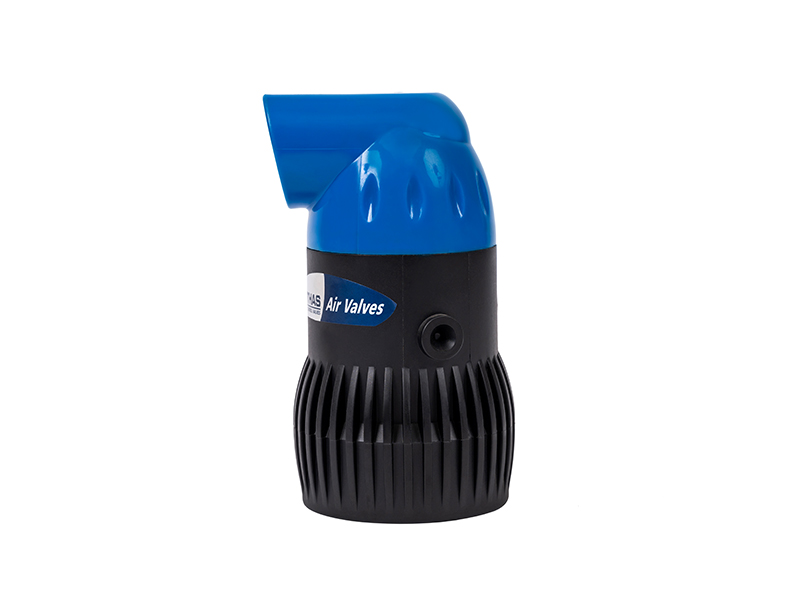
Facility managers and agricultural engineers do not install venting equipment simply to let air out. They install them to protect multi-million-dollar infrastructure. The right unit serves as a critical pipeline protection valve. It shields the entire transport network from severe mechanical stress and chemical degradation.
Imagine thousands of gallons of water hurtling through a rigid main at high velocity, only to hit a sudden, shifting wall of compressed air. This violent collision triggers hydraulic shock, commonly known as water hammer. Shifting air pockets can compress and expand violently within the pipe. By stabilizing internal pressure and safely bleeding off these pockets, the protective valve prevents the sudden velocity changes that fracture iron fittings and lead to catastrophic pipe bursts.
Metal pipelines are highly susceptible to oxidation. When trapped air remains in constant, pressurized contact with the interior walls of iron or steel pipes, it rapidly accelerates the rusting process. Continuous, automated venting removes this oxygen-rich air from the system. This effectively extends the physical lifespan of the underground infrastructure.
Precision in modern water management relies heavily on accurate data collection. When unpredictable air pockets pass through mechanical or ultrasonic water meters, they cause internal impellers to spin erratically. They can also disrupt acoustic measuring signals. This results in false, artificially inflated readings. Removing the air ensures utilities are monitoring and billing for actual liquid volume, rather than compressed atmospheric air.
The mechanical operation of these devices is a testament to simple, reliable engineering. They rely entirely on the basic principles of buoyancy and fluid displacement. They require absolutely no external electrical power source or complex wiring to function.
The physical venting process is fully automated. Typically installed at a high point in the network where air naturally congregates, the device follows a straightforward sequence. As air enters the bottom of the unit, it displaces the water currently sitting inside the main internal chamber. As the water level drops, an internal float lowers along with the fluid. The dropping float pulls away from the upper sealing mechanism, opening a precisely engineered small orifice at the top of the casing.
The internal system pressure then forcefully expels the accumulated air out through this open orifice. Once the air is completely exhausted, water rapidly rushes back into the chamber. This action lifts the float and seals the orifice tightly before any liquid can escape.
Specifically, this mechanism operates seamlessly while the pipeline remains fully pressurized. It continuously monitors and vents micro-bubbles as they form. This ensures the hydraulic baseline remains stable without ever requiring manual intervention or costly system shutdowns.
| Valve State | Internal Water Level | Float Position | Orifice Status | Action |
|---|---|---|---|---|
| No Air Present | High (Filled) | Raised | Closed | Sealing water inside |
| Air Accumulating | Dropping | Lowering | Opening | Venting trapped air |
| Air Expelled | Rising | Raising | Closing | Restoring seal |
Different operational phases demand different venting capacities. Initial filling, routine draining, and active pressurized flow all present unique hydraulic challenges. Selecting the correct mechanical design is absolutely essential for comprehensive infrastructure safety.
This is the most common iteration found in daily operations. It features a very small exhaust port. It is engineered specifically to bleed off small, continuous volumes of accumulated air while the system operates under its standard working pressure.
An air vacuum valve serves a completely different, yet equally vital, function. It features a massive orifice designed to handle extreme volumes of airflow. When a dry pipeline is initially being filled with water, this unit exhausts the displaced atmospheric air rapidly. Conversely, when a pipeline is being drained for maintenance, it acts as a vacuum breaker, admitting large volumes of outside air back into the pipe. This critical function prevents the formation of a vacuum, which could easily cause thin-walled pipes to collapse inward.
A kinetic air valve is a highly advanced variation designed explicitly for high-velocity systems. Standard units can sometimes experience a dangerous phenomenon known as premature closure. This happens when the sheer speed of the exiting air forces the internal float up, locking the valve shut before all the air is actually released. Advanced kinetic designs utilize complex aerodynamic principles to ensure the float remains securely down until the liquid actually reaches it. For instance, industry-standard 2-inch plastic kinetic models operate flawlessly across a wide pressure range of 0.1 to 10 bar, guaranteeing safe, complete pipeline filling without pressure spikes.
For maximum security, engineers frequently specify combination units. These robust devices house both a large orifice for rapid filling and draining, and a small orifice for continuous pressurized release within a single body. This provides complete protection across all phases of network operation.
Recent industry analyses highlight a growing, global emphasis on mitigating Non-Revenue Water and lowering the carbon footprint of pumping stations. As utility providers and agricultural sectors grapple with rapidly aging infrastructure and unpredictable climate patterns, there is a pronounced shift toward optimizing existing hydraulic baselines. Before investing heavily in expensive digital leak-detection sensors, engineers are looking at fundamental mechanical upgrades.
Consequently, advanced air management strategies are taking center stage. Modern fluid dynamics experts no longer view pipeline venting as an optional maintenance task. Instead, it is widely recognized as a frontline defense. Properly managing air is a highly cost-effective, mechanical method to drastically reduce daily energy consumption. It directly prevents the micro-fractures caused by unchecked hydraulic transients, aligning perfectly with global sustainability goals in water conservation.
Procuring the correct hardware requires a careful analysis of the pipeline's unique hydraulic profile. A one-size-fits-all approach inevitably leads to system inefficiencies or catastrophic failures. When evaluating fluid control components, facility managers must recognize that not all venting mechanisms are manufactured to the same exacting standards.
The operational environment of a water main is inherently harsh. Components face constant exposure to moisture, fluctuating pressures, and corrosive soil elements. High-quality units utilize robust materials tailored to specific environmental demands. For agricultural and drip irrigation networks, utilizing a dedicated irrigation air valve made from UV-resistant, glass-reinforced nylon or Polypropylene is crucial. These specialized polymers inherently resist the corrosive nature of liquid fertilizers and handle frequent, seasonal pressure fluctuations without degrading.
Proper sizing is arguably the most critical step in the procurement process. Sizing calculations depend heavily on the main pipe's diameter, the maximum flow rate, and the operational pressure. If a unit is undersized, it will not vent air fast enough during the filling process. This leads to dangerous air pocket compression. In contrast, if a unit is oversized, it may expel air too rapidly. When the water column finally reaches the oversized orifice, it slams shut with immense force, ironically causing the exact water hammer the device was meant to prevent. For standard agricultural submains, a 2-inch BSP or NPT male threaded connection is often the sweet spot for balancing intake and exhaust capacities.
Even the most precisely engineered valve is rendered entirely useless if installed in the wrong location. Standard engineering practices dictate that these devices must be installed at absolute peaks, which are the highest physical elevations within the pipeline network. Furthermore, they should be placed at changes in slope where a pipe transitions from a steep upward grade to a downward slope. On flat stretches, air drags and accumulates in imperceptible high points, so installations should occur every 1,500 to 2,500 feet. Finally, always place them immediately downstream of pumps where vortex air is frequently introduced.
Proper installation ensures that the selected equipment functions exactly as the engineers intended. Poor plumbing practices can easily compromise the internal mechanisms, leading to persistent leaks or complete operational failure.
Directly threading a venting unit into a main pipeline is a significant operational error. Maintenance is an inevitable requirement for any mechanical part. Therefore, best practices dictate that a manual isolation valve, typically a full-port ball valve, must be installed directly beneath the venting device. If the float mechanism becomes jammed with debris, technicians can simply close the isolation valve to perform necessary cleaning. This completely avoids a costly shutdown and depressurization of the entire transport network.
Because the internal mechanics rely entirely on gravity and buoyancy, the unit must be installed perfectly plumb. Installers must use a level during fitting. If the unit is tilted even slightly, the internal float will rub against the chamber walls. This friction prevents the float from rising and falling smoothly, leading to either continuous water leakage or a failure to vent trapped air when needed.
While high-quality units operate automatically, they are not entirely immune to environmental factors. Establishing a standardized, bi-annual maintenance schedule is highly recommended to ensure proactive pipeline protection.
| Maintenance Task | Frequency | Objective |
|---|---|---|
| Visual Leak Inspection | Monthly | Ensure the orifice seals completely after venting without weeping. |
| Debris Clearing | Bi-Annually | Remove sediment, rust, or mineral scale from the internal float chamber. |
| Vent Hole Check | Bi-Annually | Ensure insects or mud wasps have not built nests over the exterior exhaust port. |
| Seal Replacement | Every 3-5 Years | Replace rubber O-rings or seating seals to maintain a perfectly watertight closure. |
Managing fluid dynamics is a complex undertaking, but mitigating the dangers of trapped air does not have to be. Proper aeration management is not an optional accessory. It is a mandatory investment for the efficiency, safety, and longevity of any pressurized fluid transport system. By continuously bleeding off restrictive air pockets, these devices drastically lower pumping costs and shield rigid pipes from explosive hydraulic shocks.
Whether you are designing a massive municipal water grid or managing a sprawling farm that necessitates a chemically resistant polymer model, choosing the right hardware is paramount. Take the time to evaluate your current pipeline infrastructure carefully today. Consult with engineering experts, analyze your topographical high points, and equip your system with reliable air release valve solutions from Arka Irrigation to protect your long-term operational investments.
An air release unit features a very small orifice designed to continuously vent small, accumulated pockets of air while the pipeline remains fully pressurized during normal operation. In contrast, an air vacuum unit features a much larger orifice. Its primary function is to expel massive volumes of air quickly when a dry pipeline is being filled, and to allow massive volumes of outside air back into the pipe when it is being drained. This prevents the creation of a vacuum that could easily collapse thin-walled pipes.
For optimal performance, these devices must be installed at the absolute highest physical elevations of the pipeline topology. Additionally, they should be strategically placed at significant changes in downward slope, at regular intervals of 1,500 to 2,500 feet on long, flat horizontal runs, and immediately downstream from pumping stations where vortex air is most likely to be introduced into the water column.
While mechanically possible, it is highly discouraged in practical applications. Standard municipal or industrial units are often made of cast iron or steel, which can corrode quickly when exposed to the harsh fertilizers, chemicals, and organic debris common in agricultural water. A dedicated irrigation unit is manufactured from chemical-resistant, UV-stabilized polymers specifically engineered to withstand harsh agricultural environments and fertigation processes without degrading.
A properly functioning, high-quality unit will not leak water. The internal float is engineered to create a perfectly watertight seal against the upper orifice the exact moment water fills the chamber. If a unit is leaking or weeping continuously, it generally indicates that debris, sediment, or hard mineral scale is physically trapped between the rubber seal and the orifice, preventing complete closure. Routine maintenance and cleaning will quickly resolve this issue.
Common symptoms of trapped air include unpredictable pressure surges, water hammer during pump startup, and unusually high energy bills. You might also notice erratic readings on your flow meters or hear strange gurgling and whistling sounds coming from the pipes. If your pumps are running at full capacity but water output is noticeably lower than expected, an air block is highly likely.
Sizing depends on the flow rate and operational pressure, not just the pipe diameter. However, for a standard 2-inch agricultural submain, a 2-inch kinetic or combination valve with a BSP/NPT threaded connection is typically ideal. It provides sufficient exhaust capacity during filling and adequate vacuum protection during draining without causing premature closure or pressure spikes.


