
Views: 0 Author: Site Editor Publish Time: 2026-10-27 Origin: Site


Unexplained pipe bursts, severe water hammer, and sudden drops in water flow share a common, invisible cause. Trapped air. When air accumulates inside a piping network, it acts as a silent destroyer. It ruins plumbing, municipal, and agricultural setups from the inside out. The most effective safeguard against these pressure surges and flow restrictions is a dedicated venting mechanism.
However, purchasing high-quality hardware is only the first step in safeguarding your infrastructure. The precise location where you install it determines whether your system survives pressure fluctuations or fails prematurely. A misplaced unit offers zero protection. It leaves your pipes completely vulnerable to catastrophic ruptures.
This comprehensive guide examines the exact locations required for optimal installation. We will explore how to select the right models, outline step-by-step field practices, and help you achieve absolute pipeline stability.
Understanding the physics of air within fluid conduits is essential for long-term system longevity. Air enters piping networks through various avenues. Pumps introduce it mechanically. Unsealed joints draft air under negative pressure. Water itself carries dissolved gases. According to Henry's Law, the amount of dissolved gas in a liquid is directly proportional to its partial pressure. As water flows through a transmission main and experiences pressure drops or temperature increases, this dissolved air separates. It rapidly forms pressurized pockets.
Current industry trends in fluid dynamics reveal a massive shift toward proactive aeration management. Aging municipal grids and escalating pumping energy costs force modern engineers away from reactive leak repairs. Instead, the focus has shifted entirely to predictive pipeline protection. With changing climate conditions and fluctuating water tables, managing dissolved gases is no longer optional. It is a critical baseline for infrastructure survival. Facility managers now recognize that optimizing flow efficiency through proper venting dramatically reduces carbon footprints and operational overhead.
Trapped air creates severe mechanical hazards. It restricts the effective cross-sectional area of the pipe. This chokehold forces pumps to work exponentially harder, substantially increasing energy consumption. More dangerously, highly compressed air pockets cause severe pressure surges. When surging water rapidly compresses and expands these pockets, the resulting shockwaves shatter PVC pipes and blow out ductile iron joints. Therefore, installing a premium valve is a wasted investment if bolted into a dead zone where gas does not naturally collect. Proper placement dictates whether your system vents safely or succumbs to structural fatigue.
Identifying the correct installation nodes is the foundation of fluid dynamics management. Engineers and agricultural technicians rely on specific geometric rules to determine these locations. The following zones are non-negotiable for effective, continuous venting.
Air is significantly lighter than water. Buoyancy forces dictate that gas naturally travels to the highest elevation within a closed system. Local peaks act as primary accumulation zones. Imagine a buried municipal main conforming to the rolling hills of a suburban street. The apex of each hill represents a critical trap for separated gases. Identifying and tapping these absolute high points is mandatory. Failure to place venting hardware at these peaks guarantees the formation of massive air locks. These locks can completely halt gravity-fed flow.
Terrain variations directly dictate fluid and gas behavior. Peaks are not your only concern. An installation is required at the exact apex where a steep upward slope transitions into a downward slope. Furthermore, you must place valves where a downward slope suddenly increases in steepness, or where an upward slope decreases. These specific geometric transitions create localized zones where water velocity drops or pulls apart. This allows entrained micro-bubbles to merge and form stationary, destructive traps.
Even on perfectly flat terrain, dissolved air separates from water over extended distances. Minor pressure fluctuations and internal pipe friction cause this separation. Industry standards and hydraulic engineering guidelines dictate a strict rule. You must install a venting mechanism every 1,500 to 2,500 feet along straight, horizontal runs. This calculated spacing prevents the gradual buildup of gas that eventually restricts flow in long transmission mains.
Mechanical pumps are notorious for introducing significant volumes of air during their startup sequences. This is especially true when drawing from deep wells or partially empty reservoirs. You must place a pipeline protection valve on the immediate discharge side of the pump. This strategic placement expels the initial massive air volume before it enters the primary distribution network. It protects downstream components from sudden shockwaves and prevents the pump from becoming airbound.
Rapid valve closures create immediate and severe pressure differentials. Placing venting mechanisms near check valves and large shut-off valves prevents the formation of destructive vacuums. When the system drains or shuts down abruptly, atmospheric protection is vital. Without it, sudden negative pressure easily causes thin-walled pipes to collapse inward, destroying the entire line.
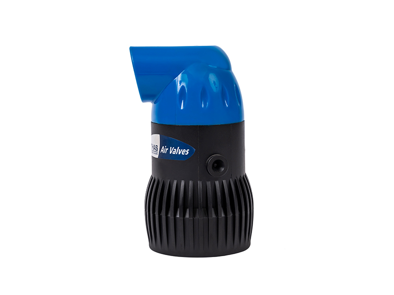
Matching the hardware to the specific installation environment is crucial for operational safety. Different nodes within a water network experience vastly different aerodynamic and hydrostatic forces. Selecting the wrong model leads to premature closure, continuous leaking, or catastrophic vacuum collapse. Use the comparison criteria below to match the technology to your field requirements.
| Valve Type | Orifice Design | Primary Function | Best Installation Location |
|---|---|---|---|
| Standard Release | Small / Pinpoint | Vents small amounts of pressurized air continuously. | System high points and long horizontal runs. |
| Vacuum Breaker | Large | Admits atmospheric air to prevent pipe collapse. | Downhill runs and system drain points. |
| Kinetic Air | Large / Aerodynamic | Discharges massive air volumes during initial filling. | Pump discharge lines and wellheads. |
| Combination | Dual Orifice | Combines continuous venting with vacuum protection. | Critical municipal peaks and main agricultural manifolds. |
This variant features a small internal orifice designed to expel minor amounts of pressurized, dissolved air continuously. It is best suited for system high points where air slowly accumulates during normal operation. The pinpoint orifice ensures the valve does not blow shut under high hydrostatic pressure. This allows for steady, controlled, and quiet venting.
Known in the industry as a vacuum breaker, this large-orifice device serves a completely different purpose. Instead of venting under pressure, an air vacuum valve admits substantial volumes of atmospheric air into the pipe. This occurs when the system is actively draining or experiencing a sudden pressure drop. This action equalizes internal and external pressure, preventing negative pressure from causing a vacuum-induced pipe collapse.
Engineered for high-velocity scenarios, a kinetic air valve discharges massive volumes of air rapidly during the initial filling of an empty system. For instance, purpose-built models like the ARKA A20 2-Inch Plastic Air Release Kinetic Valve are constructed specifically for high-capacity agricultural pipelines. Utilizing durable polymer bodies, these units feature an aerodynamic internal float. This float remains perfectly stable while high-velocity air streams past it, closing only when solid water finally reaches the chamber. This engineering eliminates the frustrating premature closure phenomenon that plagues poorly designed networks.
Complex infrastructure nodes experience both rapid filling sequences and continuous pressurized operation. Here, a combination unit is the ultimate solution. It merges the large-orifice functions of a kinetic unit with the small-orifice continuous venting of a standard release unit. By providing comprehensive protection in a single housing, combination valves remain the gold standard for critical municipal peaks.
While the laws of fluid dynamics remain constant, practical application differs significantly depending on the industry. The environmental demands of a rural farm field differ vastly from the strict regulatory requirements of a city street.
Agricultural setups face unique challenges due to uneven terrain, seasonal operation cycles, and precise emitter requirements. In these harsh environments, a dedicated irrigation air valve is a critical component for crop survival. Technicians install these units in drip irrigation manifolds, sub-main lines, and at the highest elevations of specific agricultural zones. Proper placement ensures uniform water flow to emitters across varying elevations. Specifically, it breaks the vacuum effect that sucks mud and soil into the drip lines when the irrigation pump shuts off. Without this protection, debris permanently clogs the emitters.
Municipal plumbing requires strict adherence to local building codes and engineering handbooks. Considerations for exposed city pipes include rigorous protection against freezing conditions, UV degradation, and physical tampering. In these settings, contractors house valves in insulated underground vaults or integrate them directly into secure pumping stations. Furthermore, materials must often meet stringent potable water certifications, and sizing must account for massive city-wide flow rates.
Proper mechanical execution is just as important as location selection. A poorly installed valve will leak, bind, or fail to vent entirely. Follow these empirical steps for a secure, professional-grade field installation.
Safety is always the primary concern. Before touching any tools, shut off the main water supply. Completely drain the local pipe section to relieve all internal static and dynamic pressure. Working on a pressurized line without specialized hot-tapping equipment results in severe physical injury and uncontrolled flooding.
Using a specialized hole saw or a commercial tapping saddle, drill and tap the pipe at the exact top dead center. This is the 12 o'clock position. This is a critical detail. Installing the unit anywhere else on the circumference completely fails to capture the rising air bubbles. Gas strictly hugs the highest internal surface of the pipe.
You must always install a manual ball valve or gate valve immediately between the main pipe and the primary venting unit. This isolation valve is crucial. It allows maintenance teams to shut off water strictly to the air valve for future cleaning or replacements. You will not have to shut down and drain the entire fluid network.
The internal float mechanisms inside these devices rely entirely on gravity and buoyancy. Therefore, the venting unit must be installed perfectly plumb and vertical. Use a high-quality spirit level to confirm alignment. Any deviation from a strict vertical axis causes the internal float to rub against the casing, jamming the valve open or closed.
Apply industrial-grade Teflon tape or a liquid thread sealant to all threaded connections to prevent micro-leaks. Once secured, open the isolation valve. Gradually introduce water back into the main system. Test for leaks at the joints. You should audibly hear the unit venting air as pressure builds. It must seal completely and instantly once solid water reaches the internal chamber.
Avoiding empirical errors is critical for maintaining infrastructure integrity. Even experienced technicians make these detrimental mistakes if they rush the installation process.
Installing the hardware horizontally or at a slight angle is the most frequent error. This guarantees that the float mechanism will bind against the inner casing. A jammed float renders the unit either permanently open, causing a massive water leak, or permanently closed, offering zero aeration protection.
Undersizing the valve for the pipe diameter is another critical oversight. Engineers calculate the required orifice size based on the pipe diameter and the maximum potential drainage rate. An undersized orifice creates a severe aerodynamic bottleneck. It fails to admit air fast enough to provide sufficient vacuum protection during rapid draining.
Placing the tap on the side or bottom of the pipe defeats the physics of the system. Because air always rises to the highest point, side installations completely miss the traveling air pockets. This leaves the destructive gas trapped at the top of the pipe, rendering your hardware useless.
Finally, neglecting environmental protection destroys outdoor installations. In cold climates, residual water trapped inside the valve body freezes and expands. This expansion exerts immense pressure on internal components, cracking the outer casing. Installing insulated enclosures or thermal jackets is an empirical necessity for above-ground setups.
Routine inspection extends the lifespan of your fluid management hardware and ensures continuous protection. Before performing any maintenance, technicians must ensure the isolation valve beneath the unit is fully closed. Attempting to dismantle a valve under active pressure is highly dangerous.
To verify functionality, isolate the unit using the sub-valve. Carefully bleed the pressure using the testing petcock if your model includes one. The internal float should drop freely, opening the orifice. When you reopen the isolation valve, you should hear a brief, sharp rush of air followed by a solid, watertight seal.
Signs of a failing unit include continuous water leakage from the top orifice, high-pitched whistling sounds during normal operation, or the sudden return of water hammer symptoms. These symptoms usually indicate that debris is preventing the internal seal from seating properly.
If the unit fails to seal, isolate it and carefully open the top casing. Clean any accumulated debris, mineral scale, rust, or biological growth from the internal float mechanism and the elastomeric seating gasket. These contaminants frequently compromise the watertight seal. Wash the components with a mild descaling solution and reassemble carefully.
Knowing exactly where to install venting hardware is the foundational key to a long-lasting, leak-free plumbing or irrigation system. By understanding the physics of trapped gas, you proactively defend your infrastructure against the silent threats of flow restriction and water hammer.
Always remember to target system high points, significant gradient changes, long horizontal runs, and vulnerable pump stations. A strategic installation not only prevents catastrophic pipe bursts but also significantly lowers energy costs by allowing pumps to operate at peak efficiency.
Do not wait for a pressure surge to compromise your network. Upgrade your system's safety today by sourcing reliable, high-performance venting solutions tailored to your specific hydraulic needs. Explore the professional-grade valves at ARKA to find the exact match for your pipeline infrastructure.
No. The internal float mechanism relies entirely on gravity and buoyancy to function. It must be installed perfectly vertical at the absolute top of the pipe to operate correctly. An angled or horizontal installation will cause the internal float to jam, leading to continuous leaking or total failure to vent.
Yes. Even on flat, featureless runs, venting hardware should be installed every 1,500 to 2,500 feet. This regular spacing is required to safely vent dissolved air that naturally separates from the water over long distances due to minor pressure fluctuations and internal pipe friction.
An air vacuum valve primarily pulls massive volumes of atmospheric air into the pipe to prevent a vacuum collapse during system draining. In contrast, a kinetic air valve expels large amounts of air out of the pipe rapidly during the initial filling sequence. Combination valves are designed to perform both of these critical functions in one unit.
It should be placed at the highest elevation point of the specific irrigation zone and at the extreme ends of long lateral lines. This strategic placement prevents muddy water and soil from being sucked backward into the delicate drip emitters when the system shuts off and drains.
If the water hammer is caused by compressed, trapped air pockets abruptly shifting and rebounding inside the pipe, a properly placed valve will effectively resolve the issue by eliminating the air pocket. However, if the water hammer is caused strictly by fast-closing mechanical valves without air involvement, additional surge arrestors may be required.
Sizing depends on the pipe diameter, the flow rate of the water, and the maximum potential drainage rate. As a general field rule, the valve orifice should be roughly 1 inch for every 1 foot of main pipe diameter, but you should always consult manufacturer flow charts or a hydraulic engineer to prevent aerodynamic bottlenecks.
Omitting these valves leads to severe operational failures. Trapped air will choke the water flow, forcing pumps to consume massive amounts of excess electricity. Eventually, the compressed air pockets will cause pressure surges strong enough to shatter pipes, blow out joints, or cause the pipeline to collapse inward from vacuum forces during draining.


