
Views: 0 Author: Site Editor Publish Time: 2026-10-29 Origin: Site


A sudden, unexplained pressure drop. A violent shudder echoing through the facility floor. Or worse, a catastrophic pipe burst flooding a trench and halting operations entirely. Facility managers and engineers face these nightmare scenarios when fluid dynamics are misunderstood or ignored. Fluid conveyance systems are rarely static environments. Instead, they operate as highly dynamic networks where changing flow conditions constantly create dangerous air pockets and severe vacuum voids. Pump startups, rapid valve closures, and fluctuating municipal demand trigger these extreme shifts in fluid velocity.
To combat these invisible hydraulic threats, engineers rely on a critical line of defense. The air release valve serves as the fundamental difference between a resilient pipeline and a fragile system waiting to fail. This comprehensive guide explores the exact scenarios, mechanical principles, and strategic placement methodologies required to safeguard your infrastructure.
Before specifying protective equipment, one must fully grasp the destructive forces at play within a closed piping network. The fluid inside a pipe behaves very differently when its velocity is suddenly altered.
Pipelines experience constant operational shifts that disrupt hydraulic equilibrium. A high-horsepower municipal booster pump kicking online immediately forces water forward. A sudden blackout causing an immediate system shutdown stops momentum instantly. Even automated isolation valves directing water to different facility zones trigger immediate changes in fluid velocity. Engineers refer to these sudden shifts as hydraulic transients. When water accelerates or decelerates rapidly, the resulting mechanical stress must be managed. Otherwise, the physical infrastructure absorbs the brute force of the impact, often ripping apart flange gaskets and shattering PVC joints.
Water naturally carries dissolved air. As changing flow conditions cause localized pressure drops, this air is forced out of solution. It coalesces into micro-bubbles that eventually form massive air pockets at high elevations. This phenomenon is known as air binding. It artificially restricts the cross-sectional flow area of the pipe. Consequently, the fluid velocity increases through the bottleneck, creating severe friction and head loss. The system pumps must then consume significantly more electrical energy to force water past the blockage. Left unchecked, trapped air completely vapor-locks a system, rendering it entirely inoperable.
While pressure spikes are dangerous, negative pressure is arguably the most destructive force a pipeline can encounter. When a pump suddenly loses power, the forward momentum of the heavy water column continues. This leaves a void in its wake, creating a severe vacuum. Industry professionals call this water column separation. Similarly, when a maintenance crew rapidly drains a line, the departing water acts like a massive syringe pulling back. If atmospheric air cannot enter to replace the displaced water, the internal pressure plummets. External atmospheric pressure then violently crushes thin-walled pipes like cheap plastic bottles. This leads to expensive excavations and the potential suction of toxic groundwater into clean municipal supplies.
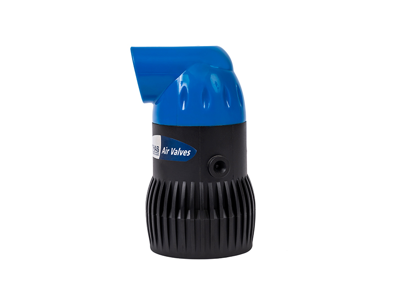
To mitigate these severe hydraulic transients, engineers utilize specialized mechanical devices designed to manage air intake and exhaust automatically, entirely without human intervention.
At its core, this device performs two vital, opposing functions. First, it acts as a massive exhaust port. It allows large volumes of compressed air to escape safely ahead of a rushing water column when an empty pipe is being filled. Second, it acts as a mechanical lung during draining or pump failure. It breathes in huge gulps of atmospheric air to break any forming vacuum. The internal mechanism relies on a precision-calibrated float. When water fills the chamber, buoyancy lifts the float to seal a large orifice. When the water recedes, the float drops instantly, opening the airway wide.
Selecting the wrong configuration is a common, yet incredibly costly, engineering mistake. Facility managers must understand the aerodynamic differences to ensure system safety.
| Valve Type | Primary Function | Orifice Size | Best Application Scenario |
|---|---|---|---|
| Standard Air Release | Vents small, accumulating bubbles under fully pressurized conditions. | Microscopic | Continuous operation at high points to prevent air binding. Cannot prevent vacuums. |
| Air Vacuum Valve | Expels and admits large volumes of air during filling or draining. | Large | System commissioning, rapid draining, and pump shutdown protection. |
| Kinetic Air Valve | Handles sonic-velocity air exhaust without premature float closure. | Large / Aerodynamic | Highly dynamic networks with aggressive, high-speed flow changes. |
Certain operational environments make the installation of these devices not just recommended, but strictly mandatory to comply with basic engineering safety standards.
Bringing a dry pipeline online is a delicate operation. The rushing water acts as a massive hydraulic piston, violently compressing the static air resting inside the pipe. If this air has no escape route, it generates severe pressure spikes. A properly placed exhaust mechanism provides a controlled exit path, allowing the system to fill smoothly without inducing mechanical shock.
Unexpected blackouts represent a worst-case scenario for fluid networks. The sudden loss of driving pressure causes immediate water column separation. As the fluid momentum carries the water away from the pump discharge, a localized vacuum cavity forms instantly. The protective valve must react in milliseconds, dropping its float to admit atmospheric air. This immediate intake cushions the returning water column and prevents the pipe walls from buckling inward.
Agricultural fluid networks face highly unique terrain challenges. Miles of piping are often laid across uneven, tractor-rutted landscapes, rolling hills, and deep valleys. Furthermore, automated irrigation systems constantly cycle on and off across different watering zones. These continuous flow changes create multiple vacuum risks across the entire farm. Deploying a specialized irrigation air valve is critical here. It prevents dirt, fertilizer, and pathogens from being sucked backward into the delicate drip emitters via the vacuum effect when the watering cycle ends.
Recent engineering trend analyses reveal a significant shift in how municipalities and large-scale agricultural operations approach fluid dynamics. As extreme weather patterns induce severe droughts and sudden flash floods, water infrastructure is pushed to its absolute limits with highly erratic demand cycles. Modern facility managers are moving away from reactive pipe repairs toward predictive, climate-resilient designs. In this evolving landscape, automated air management is no longer viewed merely as an operational enhancement. It is recognized as a baseline requirement. Integrating high-capacity kinetic valves is now the industry standard for stabilizing hydraulic gradients against the unpredictable flow transients caused by modern smart-grid pumping stations.
Investing upfront in reliable air management targets the root cause of hydraulic failures, allowing maintenance teams to focus on scheduled upkeep rather than chaotic crisis management.
Pumping water is notoriously energy-intensive. When trapped air reduces the effective internal diameter of a pipe, it drastically increases fluid friction. The total dynamic head the pump must overcome skyrockets. By automatically venting these air pockets, the system maintains its designed hydraulic efficiency. Facility operators consistently report a direct, measurable reduction in monthly electrical consumption once proper air management is implemented.
Trapped air accelerates internal degradation. Oxygen-rich pockets promote rapid corrosion and rust in metallic pipes. Meanwhile, the constant mechanical fatigue from pressure surges weakens structural supports. Eliminating these air pockets removes the excess oxygen and stabilizes internal pressures. Utilizing a dedicated pipeline protection valve adds decades to the operational lifespan of the entire conveyance system.
Procuring top-tier equipment is meaningless if it is installed in the wrong location. The physics of buoyancy dictate that air and water behave differently, meaning these components must be strategically placed to intercept air where it naturally gathers.
Because air is significantly lighter than water, bubbles naturally travel upward. They accumulate at the highest physical elevations within a piping network. Installing valves at these absolute peaks is the most critical engineering standard, ensuring the maximum volume of trapped air is captured and expelled.
Pipelines follow the contours of the landscape. Points where a downward slope suddenly becomes steeper, or an upward slope flattens out, act as natural traps for moving air. Placing valves at these gradient transitions prevents smaller micro-bubbles from coalescing into massive, destructive air pockets during aggressive flow changes.
Even in seemingly perfectly flat pipelines, fluid friction causes dissolved air to separate over long distances. If fluid velocity is insufficient to push these bubbles to a high point, they will stagnate. For extended horizontal runs, engineers mandate specific spacing intervals. Typically, installing a valve every 1,500 to 2,500 feet guarantees comprehensive air extraction across the entire network.
Navigating the specification process requires a rigorous analysis of your facility parameters. To ensure the chosen component handles the anticipated hydraulic stress, follow these specific selection criteria rather than relying on guesswork.
Selecting the correct orifice size is a precise mathematical exercise based on maximum flow rates and pipe diameter. If the intake orifice is too small, it chokes the incoming atmospheric air during a rapid drain, failing to prevent a pipe-crushing vacuum. Conversely, if the exhaust orifice is excessively large, air escapes too quickly. This causes the approaching water column to slam into the valve housing, inducing a secondary water hammer.
The construction materials must survive the fluid and environment they contact. Clean municipal water systems generally utilize epoxy-coated ductile iron. However, agricultural landscapes are exposed to harsh ultraviolet rays, corrosive chemical fertilizers, and physical impacts. For these demanding environments, specifying a 2-inch kinetic air valve constructed from high-strength reinforced nylon polymer offers superior durability and absolute rust prevention.
Highly dynamic systems experience aggressive, high-velocity air discharge. In standard designs, rushing air catches the internal float and slams it shut prematurely, trapping a dangerous pocket of highly compressed air. Upgrading to a kinetic design solves this aerodynamic flaw. The specialized internal geometry allows air to escape at sonic velocities without lifting the float. The mechanism only seals when physical liquid enters the chamber. Therefore, an air vacuum valve with kinetic properties is the superior choice for volatile flow conditions.
Long-term reliability depends heavily on meticulous installation procedures and a commitment to scheduled maintenance. Because these devices operate silently in remote locations, they are often forgotten until a catastrophic failure occurs.
Before integration, the main pipeline must be aggressively flushed to clear construction debris, welding slag, and plastic shavings. These contaminants easily jam the float mechanism. The unit must be installed perfectly vertical. Even a slight tilt causes the internal float to bind against its guide rails. Additionally, a manual isolation valve like a standard ball valve must be installed directly beneath the unit to allow for safe servicing without shutting down the entire facility.
Systems subjected to frequent flow changes require rigorous inspections due to increased mechanical wear on the rubber seals. Facility teams should conduct visual exterior checks bi-annually for weeping leaks or mineral scale. Annually, the isolation valve should be closed, and the unit drained to verify the float drops smoothly. For raw water applications, the upper housing should be periodically dismantled to clean algae or grit from the internal components.
Changing flow conditions are an unavoidable reality in modern fluid conveyance systems. However, the severe pipeline damage associated with these hydraulic transients is entirely preventable. An air vacuum release valve is not an optional accessory. It is a mandatory safeguard that protects structural integrity, slashes energy consumption, and prevents catastrophic environmental contamination. By understanding your system vulnerabilities and strategically deploying aerodynamic valves, you transform a fragile pipeline into a resilient infrastructure network. Secure your infrastructure today by exploring the robust, field-tested solutions available at ARKA Irrigation. Whether you require UV-resistant agricultural components or high-capacity kinetic valves, choosing the right product prevents catastrophic failures and ensures long-term operational efficiency.
Proper sizing depends on the pipeline diameter, the maximum fluid flow rate, and the topographical slope of the installation site. As a general industry rule, the valve diameter should be approximately one inch for every one foot of main pipeline diameter, but highly dynamic systems require complex calculations based on the maximum potential draining rate to ensure the vacuum break capacity is sufficient.
Yes, because they contain water during pressurized operation, standard models are susceptible to freezing, which shatters the internal housing. For cold climates, engineers must specify frost-proof models, install thermal insulation jackets, or utilize kinetic valves designed to drain completely dry when the system is not actively pumping water.
No. A standard model features a microscopic orifice designed solely for venting tiny bubbles of accumulated air while the system remains under pressure. It simply cannot admit atmospheric air fast enough to prevent a vacuum during rapid pipeline draining or a sudden pump failure. Using the wrong type leaves your pipes highly vulnerable to implosion.
The primary difference lies in the internal aerodynamics. A kinetic design is specifically shaped so that high-velocity air escaping the pipe will not accidentally blow the internal float shut before all the air is evacuated. It guarantees that the exhaust port stays fully open until the actual water column reaches the chamber, making it exceptionally safe for aggressive flow changes.
Operating a fluid system without proper air and vacuum management guarantees long-term operational issues and invites sudden catastrophic failures. Systems remain highly susceptible to pipe collapse from negative pressure, blown joints from water hammer, and severe degradation of pump impellers due to air binding. Furthermore, energy costs rise significantly as pumps are forced to work harder to push water past trapped air pockets.


