
Views: 0 Author: Site Editor Publish Time: 2026-11-01 Origin: Site


Clogged micro-emitters and fouled solenoid valves create relentless operational bottlenecks. Left unchecked, abrasive sediment and particulate debris will rapidly degrade expensive downstream infrastructure. Installing a robust mechanical barrier is not just good practice—it is the foundational defense layer for any commercial water treatment array.
Current field data highlights a distinct pivot in agricultural and industrial fluid management. Driven by water scarcity and strict environmental compliance, facility managers are abandoning oversized, water-wasting setups. The industry standard now demands highly calibrated filtration arrays designed to minimize flush-cycle wastewater. Consequently, dialing in precise installation parameters—specifically spatial geometry and hydraulic capacity—has become critical for long-term sustainability and regulatory adherence.
Procuring standard hardware only solves half the problem. Incorrect deployment frequently triggers severe pressure loss, systemic leaks, and frustrating maintenance hurdles. Poor spatial planning or ignoring fluid dynamics can cripple an otherwise perfectly engineered plumbing network. This technical guide breaks down the exact specifications required for a flawless setup. By calculating accurate flow rates, establishing proper ground clearance, and executing a standardized installation sequence, operators can guarantee maximum equipment lifespan.
A filtration unit operates as a physical checkpoint within a pressurized pipeline. It utilizes a precisely woven stainless steel or durable molded plastic cylinder to intercept suspended solid particulates from the source fluid. As water travels through this microscopic grid, abrasive materials larger than the designated micron rating are trapped. This vital process prevents destructive debris from tearing through delicate downstream seals and pump impellers.
Among the various configurations deployed in the field, the Y-type screen filter remains the industry workhorse due to its geometric versatility. The angled branch allows for seamless integration into both horizontal and vertical pipe runs while keeping the primary maintenance port highly accessible. Modern agricultural setups frequently rely on this specific design to protect extensive micro-irrigation networks from well-water sand.
From a systems engineering perspective, this hardware acts as the primary pre-filtration stage. Finer mechanisms, such as reverse osmosis membranes or delicate carbon blocks, would rapidly foul without this initial line of defense. Advanced units, like those engineered by ARKA, utilize reinforced polyamide housings and heavy-duty 120-mesh stainless steel elements to withstand harsh environmental conditions and high-pressure spikes.
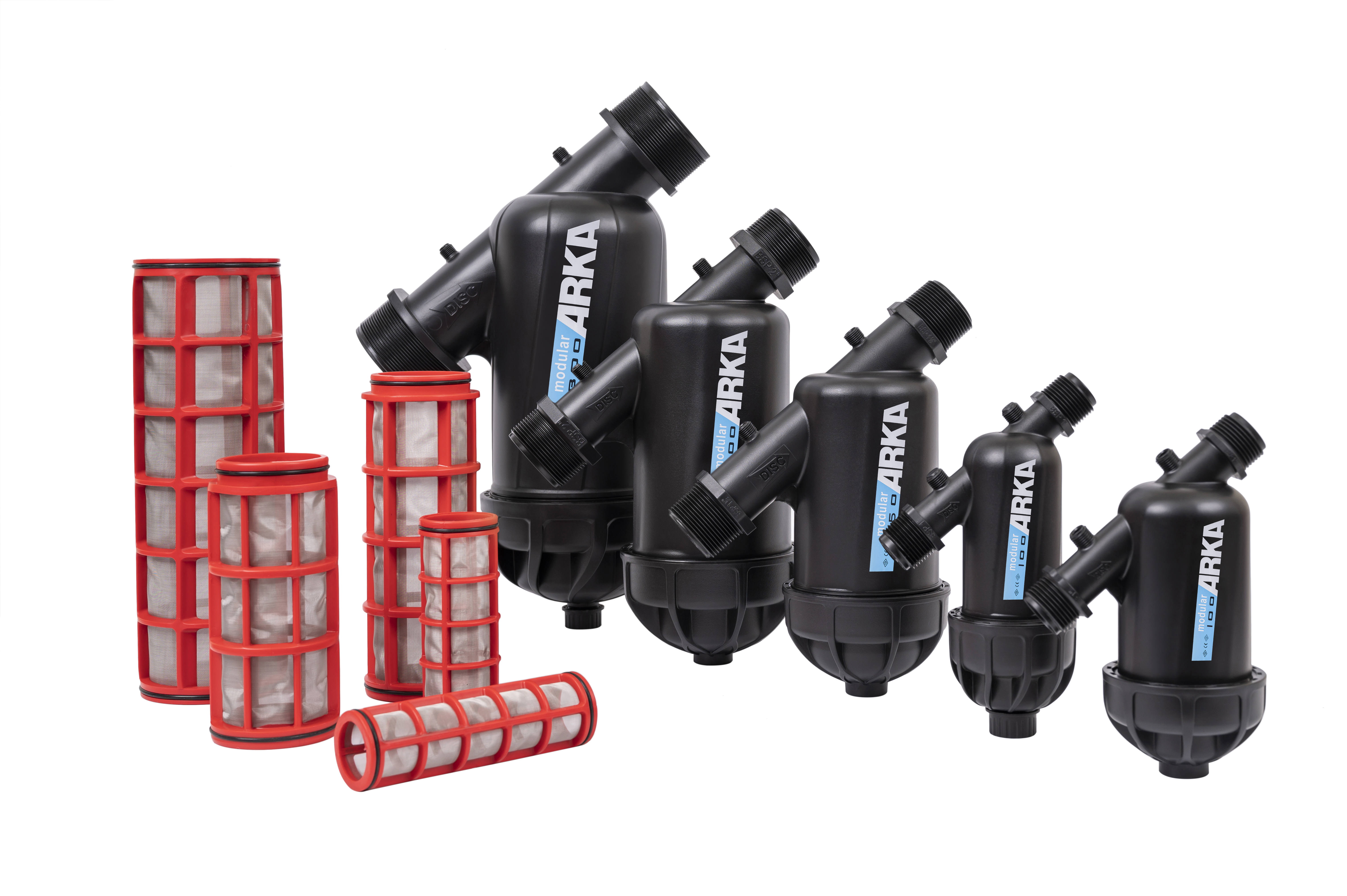
Spatial planning is notoriously overlooked during the initial drafting phase of plumbing expansions. Failing to account for physical dimensions results in setups that look great on paper but are practically impossible to service in the field.
Imagine wedging a standard 5-gallon utility bucket under a flush valve sitting a mere two inches off a concrete slab. The resulting mess is entirely preventable. A main housing should never be installed flush against a foundational baseboard. When the purge valve opens to expel accumulated sediment, that wastewater requires a designated escape route. Engineering best practices dictate leaving a vertical buffer of at least 12 to 18 inches beneath the lowest point of the assembly. This gap provides ample room to position a collection basin or securely attach a threaded drainage hose.
Routine maintenance demands the physical removal of the internal cylindrical mesh for deep cleaning. Operators must calculate the exact spatial envelope required to unthread the end cap and slide the element completely out of the main body. A reliable field rule is to measure the total length of the internal replacement cartridge and double that exact measurement. This figure represents the absolute minimum linear clearance required. Ignoring this metric forces technicians to dismantle the surrounding piping infrastructure just to service the screen filter system.
Maintenance frequency correlates directly with physical accessibility. If a unit is wedged into a cramped subterranean vault or bolted excessively high on a pump house wall, operators will inevitably neglect routine flushing schedules. For wall-mounted applications, positioning the central housing at chest height optimizes ergonomic access. This specific elevation allows technicians to apply maximum torque when loosening a stubborn cap without straining their lower backs.
Selecting hardware based solely on your existing pipe diameter is a critical engineering misstep. System sizing must be dictated by hydraulic dynamics—specifically the delicate balance between fluid velocity and mechanical resistance.
Flow rate is measured in Gallons Per Minute. When pressurized water is forced through a restrictive microscopic barrier, it generates friction. This resistance creates a measurable pressure drop, scientifically referred to as Delta P. If the incoming volume exceeds the maximum rated capacity of the housing, fluid velocity spikes aggressively. This severe restriction starves downstream irrigation zones of necessary operational pressure while simultaneously accelerating wear on the stainless steel wire fibers.
To prevent systemic starvation, operators must match their pipe diameter and flow requirements to the correct hardware class. The following reference table outlines standard hydraulic thresholds for optimal performance.
| Pipe Diameter | Max Flow Rate Capacity | Recommended Application | Ideal Mesh Size |
|---|---|---|---|
| 3/4 Inch to 1 Inch | Up to 25 GPM | Residential drip lines, small greenhouses | 120 Mesh |
| 1.5 Inch to 2 Inch | 50 to 110 GPM | Commercial landscapes, light agriculture | 120 - 150 Mesh |
| 3 Inch to 4 Inch | 200 to 350+ GPM | Heavy agricultural arrays, municipal wells | 80 - 120 Mesh |
While standard residential units handle basic municipal supplies, agricultural well systems and commercial cooling towers demand elevated capacities. In these high-volume scenarios, upgrading to a large flow screen filter becomes mandatory. Premium ARKA large flow units are explicitly engineered to process up to 50 cubic meters per hour. Their expanded internal geometry distributes the water volume evenly across a massive surface area, allowing high volumes to pass through simultaneously while preserving stable downstream Pounds per Square Inch.
Executing a flawless installation requires strict adherence to a standardized operating procedure. Prior to cutting into any plumbing infrastructure, complete a thorough site assessment to mitigate the risk of catastrophic leaks.
Begin by identifying the existing pipe material—be it Schedule 40 PVC, high-density polyethylene, or copper. Accurately measure the outer diameter to ensure thread compatibility. Verify whether the fittings require National Pipe Thread or British Standard Pipe standards. Mismatching these threading profiles will guarantee a high-pressure leak.
Assemble all necessary equipment before shutting off the main supply. Secure two adjustable pipe wrenches, high-density Teflon tape, appropriate PVC primer and cement, a calibrated pipe cutter, and safety goggles. Finally, locate the primary shut-off valve. Once closed, open the lowest faucet in the downstream network to depressurize the lines and drain residual fluid. Slicing into a fully pressurized line poses severe safety risks and guarantees a flooded workspace.
Adhering to authoritative installation protocols ensures structural integrity and a leak-free lifespan. Follow this sequential engineering process.
Every commercial housing features a directional arrow molded directly into the exterior plastic or metal. This arrow must point in the exact direction of fluid travel. Reversing this orientation forces water against the weak side of the internal mesh, leading to immediate structural collapse. The angled branch containing the element must point downward. This specific angle leverages gravity to pull suspended debris into the flush basin, keeping the primary fluid pathway unobstructed.
Using a dedicated cutter, make clean and perpendicular cuts into the main line. Remove a section of pipe matching the exact length of the housing, plus the required space for threaded adapters. It is absolutely critical to deburr the inner and outer edges of the cut pipes. Any plastic shavings or copper burrs left behind will immediately wash into your new equipment upon activation, causing permanent abrasive damage to the pristine wire mesh.
Proper sealing technique is mandatory for threaded fittings. Apply high-density Teflon tape to the male threads, wrapping strictly in a clockwise direction. Apply three to five tight wraps. Wrapping counterclockwise causes the tape to unravel during insertion. Use extreme caution when tightening plastic housings. Over-torquing with heavy pipe wrenches is the leading cause of microscopic hairline fractures that eventually rupture under operational pressure. Tighten firmly by hand first, followed by a gentle quarter-turn with a wrench.
For commercial facilities or critical agricultural setups that cannot afford unexpected downtime, integrating a three-valve bypass loop is highly recommended. This configuration routes a parallel pipe around the main unit, controlled by heavy-duty isolation valves. A bypass allows operators to isolate and depressurize the hardware for deep cleaning while temporarily supplying unfiltered water to keep the property operational.
Before finalizing your system architecture, validate your equipment selection based on the specific water profile of your site.
Mesh-based units excel at capturing inorganic debris. If the source water contains coarse sand, silt, gravel, or calcified pipe scale, the rigid stainless steel wire provides an easily cleanable, two-dimensional surface barrier. They are highly cost-effective and straightforward to maintain in well-water applications.
Conversely, disc filters utilize stacked, grooved plastic rings to create three-dimensional depth filtration. Engineers explicitly specify disc variants to capture organic debris—such as algae, moss, and biological matter—which would otherwise smear across and blind a standard wire mesh.
Ultimately, if your site evaluation indicates well-water sand or municipal rust flakes, the traditional stainless steel mesh approach remains the most empirically sound and efficient choice.
The installation is not complete until the network has been rigorously tested under standard operating conditions and a strict maintenance schedule is established.
Executing the Leak Test: Slowly open the main supply valve. Allowing fluid to rush in at full velocity creates a destructive water hammer effect, potentially shattering new seals. Listen closely for the unmistakable hiss of a micro-leak and visually inspect all threaded connections. If pressure gauges are installed on either side of the unit, record the initial baseline reading.
Routine Purging: The frequency of opening the bottom purge valve depends entirely on the incoming sediment load. High-sediment agricultural wells may require daily attention, while residential municipal supplies might only necessitate monthly purging. Open the valve for 15 to 30 seconds until the expelled wastewater runs completely clear.
Chemical Deep Cleaning: When the pressure drop across the unit exceeds 7 to 10 PSI, routine flushing is no longer sufficient. Isolate the unit, depressurize the housing, and extract the element. Gently scrub the surface with a soft-bristle brush. If heavy mineral calcification is present, soak the metal cylinder in a mild acid solution—such as standard white vinegar—for 30 minutes to dissolve the calcium buildup before rinsing thoroughly and reinstalling.
Meticulous spatial planning prevents years of maintenance frustration. Guaranteeing adequate vertical clearance ensures effortless flushing and rapid element extraction. Furthermore, calculating fluid dynamics accurately stops severe pressure loss before it ever begins. Forcing high volumes through undersized components will inevitably choke your entire plumbing network.
By matching your hardware to the actual capacity demands of your facility and following strict directional guidelines, you ensure peak mechanical performance. A correctly executed setup acts as an invisible, impenetrable shield. It protects delicate downstream investments and guarantees a smooth, uninterrupted water supply for years to come. For operators looking to upgrade their infrastructure, exploring professional-grade solutions through ARKA's specialized filtration lineup ensures you have the exact specifications required for your specific water profile.
Yes, vertical installation is perfectly acceptable and common in tight pump houses. However, the fluid must be traveling downwards. This downward trajectory ensures that gravity assists in pushing the accumulated debris into the clean-out trap, preventing sediment from falling back into the incoming line when the system is depressurized.
A clean, correctly sized unit should exhibit a minimal pressure drop, typically registering between 1 and 3 PSI. If the drop exceeds 7 to 10 PSI during normal operation, it indicates that the mesh is heavily clogged and requires immediate manual cleaning, or that the overall system capacity demands a significantly larger unit.
If sized correctly according to your system's exact flow rate, it will not noticeably reduce downstream pressure. However, if the capacity rating of the installed hardware is lower than your actual flow rate, or if the internal mesh becomes obstructed with debris over time, you will experience a severe and problematic reduction in baseline pressure.
Stainless steel elements are highly durable and engineered to operate for several years with consistent, routine cleaning. Replacement is generally only necessary if the metal becomes physically torn by sharp gravel, structurally deformed by a severe water hammer event, or heavily calcified with minerals that cannot be dissolved via acid soaking.
Mesh size refers to the number of holes per linear inch of the screen. A higher mesh number means more holes, which translates to a finer screen. Micron rating measures the actual physical size of the particles that can pass through those holes. Therefore, a higher mesh number corresponds to a lower micron rating. For example, a 120-mesh screen filters out particles down to roughly 130 microns.
The most accurate method is monitoring pressure gauges installed before and after the housing. A pressure differential exceeding 10 PSI is a definitive indicator of a clog. Without gauges, you will notice a drastic reduction in water flow at your end-use points, such as sputtering irrigation emitters or a loss of pressure at commercial spray nozzles.


