
Views: 0 Author: Site Editor Publish Time: 2026-10-28 Origin: Site


Trapped air inside piping networks acts as a silent, highly destructive force. While it may seem harmless, accumulated gas easily bursts high-strength pipes, drastically reduces pump efficiency, and causes severe water hammer transients. Conversely, rapid system drainage without adequate air intake creates a vacuum powerful enough to collapse large-diameter mains inward.
Most system designers know air management components are essential. However, improperly sizing these units proves just as damaging as omitting them entirely. Undersized units lead to catastrophic pipe collapse. In contrast, oversized units cause premature dynamic closure and violent pressure surges. This technical guide explores the exact fluid dynamic principles, formulas, and practical field considerations required to accurately size these critical components for fluid networks.
The waterworks and agricultural irrigation sectors are currently experiencing a significant shift toward digital hydraulic modeling. With extreme weather events causing unpredictable flow demands, modern infrastructure requires highly resilient air management. Engineers are moving away from static spreadsheet estimates. Instead, they rely on transient surge analysis software to simulate real-world water hammer scenarios. This data-driven approach ensures that valve selection is based on precise dynamic stresses rather than outdated rules of thumb, significantly extending the lifespan of aging piping networks.
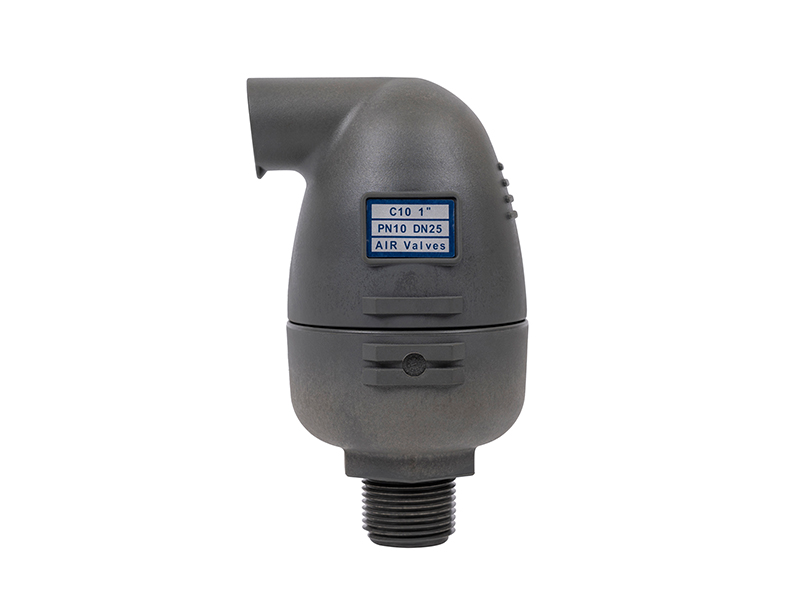
Before executing complex sizing calculations, field contractors and engineers must understand the specific fluid dynamic anomalies these components resolve. Air accumulation remains an inevitable phenomenon in fluid transport. Mitigating its physical effects is critical for long-term structural integrity.
Air infiltrates piping networks through multiple avenues. Pumps draw in air via vortexing at the intake basin. Pipelines naturally fill with atmospheric air when drained for maintenance. Furthermore, the water itself contains dissolved air, typically about two percent by volume at standard temperature and pressure. As fluid pressure drops or temperature rises, this dissolved air comes out of solution to form micro-bubbles.
Eventually, these bubbles coalesce at topographical high points. They create massive air pockets that restrict the internal cross-sectional diameter of the pipe. This invisible bottleneck significantly increases friction and head pressure. Supply pumps must then work exponentially harder to maintain the required flow rate. This leads to decreased mechanical efficiency, accelerated impeller wear, and bloated energy consumption. In severe scenarios, trapped air completely blocks fluid flow, causing a frustrating condition known as air binding.
Beyond optimizing daily operational efficiency, mitigating trapped gas is a strict structural safety requirement. An accurately engineered pipeline protection valve functions as an essential failsafe mechanism against catastrophic pressure anomalies.
During pump startup or rapid valve actuation, trapped air pockets act like highly compressible springs. When an accelerating solid water column impacts these stationary air pockets, the kinetic energy is absorbed and violently rebounded. This causes severe pressure transients commonly known as water hammer. These localized pressure spikes can easily exceed the burst rating of the pipe material, shattering joints and flanged connections. Specifically, during a sudden pump failure or rapid line drainage, the exiting water mass creates a destructive internal vacuum. Without a mechanism to admit atmospheric air rapidly, the negative internal pressure will easily crush thin-walled pipes.
System designers must identify the correct valve classification before calculating exact orifice dimensions. Sizing methodologies vary entirely based on the mechanical function the valve performs under specific pressure conditions.
An air vacuum valve features a large aerodynamic orifice designed to handle massive volumetric flow rates at very low differential pressures. Its primary function is twofold. It discharges large quantities of air when the pipeline is initially filling with water. It also admits massive volumes of atmospheric air when the pipeline is draining.
Sizing this specific classification focuses strictly on the maximum volumetric flow rates of the system. You must look at the absolute maximum fill rate of the pump and the gravity-driven drainage rate. Importantly, this type of valve seals completely shut once the system is pressurized and does not operate during normal fluid transport.
Engineered with a much smaller orifice and a specialized internal leverage mechanism, this unit continuously vents small pockets of accumulated air while the pipeline is fully pressurized. Sizing this component requires analyzing the maximum operating pressure of the system and calculating the estimated volume of dissolved air that will constantly separate from the fluid. If the orifice is miscalculated against the working pressure, the internal float will lack the buoyancy required to open the seal.
A combination valve integrates both large and small orifice functions into a single housing. It combines a kinetic mechanism for high-volume exhaust and intake with an automatic release mechanism for pressurized venting. Sizing a combination unit is a dual-step process. Engineers must calculate the requirements for both the large and small orifices independently to guarantee comprehensive system protection.
Mathematical sizing requires gathering specific operational parameters from the hydraulic design. Without precise data points, selecting a valve becomes a dangerous guessing game that jeopardizes the entire infrastructure.
The volumetric flow rate acts as the foundational metric for sizing the large orifice. Engineers must determine two distinct rates. First is the maximum filling rate, which is the absolute highest possible output of the supply pumps. Second is the maximum draining rate, representing the fastest pace the pipe will empty during a blowout or routine gravity drain scenario.
The structural rigidity of the pipeline material dictates exactly how large the vacuum relief orifice must be. Picture a municipal contractor laying miles of high-density polyethylene. While highly durable against internal pressure, this material is highly susceptible to negative internal pressure. Thin-walled materials require significantly larger air intake valves to ensure the internal pressure never drops below the specific failure threshold of the material, which can be as little as negative two PSI for certain plastics.
The standard and maximum working pressures are crucial for sizing the small orifice of a release unit. As pressure increases, the force holding the internal seal closed also increases. If the orifice is too large for a high-pressure system, the float will not have enough physical mass or leverage to pull the seal away from the orifice. This renders the valve useless.
The topographical gradient directly dictates the velocity of gravity drainage. A steeper downward slope accelerates water evacuation exponentially. This rapid evacuation demands a correspondingly higher air intake rate to prevent a vacuum from forming. Accurate topographical profiles are essential for determining these localized drainage velocities.
With operational parameters firmly established, engineers can proceed with three-phase sizing calculations to ensure the infrastructure remains protected under all dynamic conditions.
This is universally considered the most critical sizing scenario. If the valve cannot admit atmospheric air fast enough during a rapid drainage event, the pipe will buckle and collapse inward.
First, calculate the maximum drainage rate using standard gravity flow formulas based on the maximum downward slope of the pipe. Next, convert this drainage water flow rate into an equivalent air flow requirement. For instance, one thousand gallons per minute of water exiting the pipe requires exactly 133.7 standard cubic feet per minute of air entering the pipe to replace it. The golden rule of vacuum protection dictates that the valve must admit this required air volume without allowing the internal pipe pressure to drop below the safe differential pressure limit of the specific pipe material.
When filling an empty main, the atmospheric air inside must be expelled at the exact same rate the new water enters. Determine the absolute maximum pump filling rate and select a large orifice capable of exhausting air at this exact volumetric pace.
However, designers must be wary of dynamic closure risk. If the valve is undersized, the escaping air velocity becomes too high. According to Bernoulli principles, this high velocity creates a localized low-pressure zone that aerodynamically sucks the float shut before all the air is vented. This traps a massive air pocket, resulting in a destructive water hammer when the water column finally impacts the closed valve. Using a properly engineered kinetic air valve with an aerodynamic float design helps prevent this issue.
Once the line is completely full and pressurized, the small orifice takes over to vent the micro-bubbles that continuously form from dissolved gases. Calculate the volume of entrained air. The conservative industry standard assumes dissolved air constitutes roughly two percent of the maximum water flow rate.
For a water flow of two thousand gallons per minute, the continuous air venting requirement is approximately 5.35 cubic feet per minute. You must then cross-reference this required volume with the maximum operating pressure of the system using specific air release valve capacity charts to ensure the orifice can handle the volume under load.
A quick reference comparison helps clarify the distinct operational parameters for different valve classifications.
| Valve Type | Primary Function | Key Sizing Metric | Operating Phase |
|---|---|---|---|
| Air Release Valve | Vents small amounts of dissolved air | Max Operating Pressure & 2% Flow Rate | Fully Pressurized |
| Air Vacuum Valve | Large volume intake/exhaust | Max Pump Fill Rate & Gravity Drain Rate | Low Pressure / Emptying |
| Combination Valve | Dual continuous venting & vacuum protection | Calculated independently for both orifices | All Phases |
Agricultural networks present unique hydraulic challenges requiring specialized sizing approaches. Standard municipal waterworks formulas cannot always be applied directly to sprawling irrigation systems.
Drip tape and micro-irrigation systems operate at exceptionally low pressures, often hovering between ten to thirty PSI. Standard municipal valves require high internal pressure to force the float seal tightly against the orifice. In a low-pressure agricultural setup, a standard valve may lack the pressure needed to seal, resulting in continuous wasteful leaks.
Therefore, specifying an irrigation air valve requires selecting models with specialized soft-sealing mechanisms. For instance, utilizing a one-inch plastic air valve designed specifically for agricultural equipment ensures drip-tight closure at pressures as low as two to three PSI. These specialized kinetic units are constructed from durable, UV-resistant polymers to withstand field conditions while maintaining extreme sensitivity to low-pressure differentials.
Agricultural water is rarely pristine. It frequently carries suspended solids, algae, sand, and highly corrosive dissolved fertilizers. When sizing and selecting valves for these harsh applications, field engineers must account for debris buildup. This involves choosing valves with elongated bodies to keep the dirty water far away from the sealing mechanism. Conical internal shapes prevent debris accumulation, and significantly larger internal clearances mitigate clogging risks.
Calculating precise orifice dimensions is only half of the engineering equation. The most accurately sized valve will be rendered completely ineffective if installed in the wrong location. Fluid dynamics dictate that air will always seek the path of least resistance and highest elevation. Strategic placement is mandatory.
The absolute peak of any pipeline elevation profile serves as the most critical installation point. As water flows over a hill, pressure drops, dissolved air separates, and bubbles naturally accumulate at the apex. A combination valve must be placed at every localized high point to expel this gas before it becomes highly pressurized upon pump restart.
While absolute high points are obvious, changes in the downward pipeline slope are frequently overlooked. When a pipeline transitions from a gentle downward slope to a steep downward slope, water velocity accelerates. This sudden acceleration can cause the fluid to shear away from the trapped air, leaving air pockets stranded at the inflection point. Placing a valve at these gradient intersections prevents localized air binding.
In perfectly flat terrain, air lacks a natural high point to accumulate. Instead, it travels along the top inner wall of the pipe, creating a continuous layer of trapped gas that increases friction and promotes internal pipe corrosion. For long flat horizontal runs, industry engineering standards recommend installing an appropriately sized combination valve every fifteen hundred to twenty-five hundred feet to systematically vent this dissolved air.
Even experienced contractors frequently fall into sizing traps that severely compromise system integrity. Avoiding these empirical errors is critical for long-term pipeline protection.
The most prevalent and financially wasteful mistake is assuming that a six-inch water pipe automatically requires a six-inch air valve. Valves are sized strictly on volumetric air flow requirements and differential pressure limits, never nominal pipe diameter. Selecting a valve simply to match the flange size almost always results in massive oversizing. This increases capital costs and introduces severe operational risks.
Designers often size the vacuum intake based solely on how fast the water drains. They forget to verify the structural limits of the pipe material. If a contractor uses thin-walled plastic pipe but sizes the valve based on the robust differential pressure limits of ductile iron, the plastic pipe will collapse during a rapid drainage event. The valve simply will not open fast enough at the lower pressure threshold.
Accurate sizing remains the cornerstone of longevity and safety in municipal and agricultural fluid networks. You must carefully balance filling rates, drainage velocities, and operating pressures to ensure total protection. Field selection is not a place for guesswork or outdated estimation rules.
To safeguard your infrastructure and optimize pump efficiency, always specify purpose-built fluid control components. Evaluate your specific system requirements, review detailed technical performance curves, and explore the comprehensive range of high-performance air management solutions at ARKA Irrigation to find the exact valve engineered for your exact operational parameters.
In the waterworks industry, these terms are often confused. An air release valve features a small orifice designed to vent continuous, small amounts of dissolved air while the system remains under full operating pressure. Conversely, an air vacuum valve features a large orifice to handle massive volumes during filling or draining but seals shut completely under pressure.
Symptoms of an undersized valve manifest through system inefficiency and physical stress. You may observe sluggish water flow, reduced pump capacity, or higher than normal energy consumption at the pump station. Physically, you might notice pipe vibrations, erratic pressure gauge readings, or visible deformation of thin-walled plastic pipes during drainage events.
No. A pure kinetic air valve is designed solely for large-volume air management during the filling and draining phases. It utilizes a large orifice that remains open only when system pressure is very low. Once the pipeline is fully pressurized, the kinetic valve seals completely shut. If your system requires continuous venting of dissolved air pockets during normal operation, you must install a combination valve.
There is no universal static number, as placement is dictated entirely by the specific topography of the pipeline route. At an absolute minimum, you require one valve at every topographical high point and at significant changes in the downward pipe gradient. If the one-mile stretch is completely flat, engineering standards dictate placing one valve every fifteen hundred to twenty-five hundred feet.
Installing a unit incorrectly completely neutralizes its function and creates immediate hazards. The internal floats rely on gravity and precise fluid buoyancy to operate. If inverted, the float will permanently block the orifice, preventing any air from escaping during filling and failing to admit air during drainage, which can lead to immediate pipe collapse.
Yes, routine maintenance is essential, particularly in agricultural or raw water applications. Debris, mineral buildup, or algae can foul the internal sealing mechanism, causing the valve to either stick open and leak water, or stick closed and fail to vent air. Engineers recommend inspecting and flushing these units at least twice a year.


