
Views: 0 Author: Site Editor Publish Time: 2026-10-05 Origin: Site


Imagine standing at the wellhead on a freezing morning. You pump the heavy iron handle aggressively, expecting a rush of water. Instead, you feel the hollow, useless resistance of empty air. Your system has lost its prime. Diagnosing and fixing this frustrating issue feels nearly impossible without a clear visual blueprint. A proper schematic solves this exact problem by mapping out the invisible physics buried deep underground.
In this comprehensive guide, we will decode these technical drawings. You will learn to seamlessly install, maintain, or repair your manual water extraction setup. Since these systems rely entirely on the physics of atmospheric pressure and suction, the unsung hero of the entire operation is the directional regulatory network.
Before attempting to interpret complex engineering schematics, you must grasp the physical reality of the equipment standing in your yard. In modern hydrogeology and plumbing standards, a shallow well is strictly defined by the depth of its water table. Typically, this refers to a static water level that sits 25 feet or less below the surface interface. Because manual extraction relies on atmospheric pressure pushing down on the aquifer rather than mechanical force pushing up from below, systems are strictly bound by this physical depth limit.
When reviewing a technical drawing of a manual water extraction system, three primary component categories will always dominate the page. Grasping their physical function makes reading the blueprint highly intuitive.
A specialized layout diagram shows exactly how fluid is captured, lifted, and held within a plumbing network. To the untrained eye, it might just look like a chaotic series of intersecting lines and geometric shapes. However, every single symbol represents a highly specific mechanical action.
Engineers and plumbers utilize standardized symbology to ensure drawings are universally understood across the industry. Below is a reference guide for the most common symbols found on a manual extraction schematic.
| Diagram Symbol | Component | Function in the System |
|---|---|---|
| Triangle pointing up | Standard Inline Unit | Indicates the allowed direction of water flow. Water moves toward the point but cannot reverse. |
| Circle with a Diagonal Line | Flapper-Style Mechanism | Represents a hinged gate swinging open under suction and dropping shut under gravity. |
| Triangle with a Grid Base | Bottom Intake with Strainer | Denotes a directional unit located at the intake point, equipped with a protective debris screen. |
| Solid Horizontal Line | Static Water Level | Shows where the fluid naturally rests inside the casing when the system is idle. |
| Dashed Horizontal Line | Dynamic Water Level | Indicates where the water level drops to while actively drawing fluid. |
When you first unroll your layout plan, your eyes should immediately trace the central drop pipe downward. The primary regulatory mechanism is almost universally located at the absolute lowest point of the internal pipe assembly. Moving upward, particularly in older cast-iron pitcher designs, you will also notice a secondary layout detailed inside the cross-section of the above-ground cylinder itself.
A frequent source of frustration when reading plumbing diagrams is the interchangeable use of terminology. While both devices serve the exact same physical purpose of allowing fluid to travel in only one direction, their specific designs and placements on the schematic differ significantly.
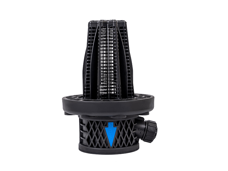
Designed for complete submersion, the bottom intake is a highly specialized variant. On a diagram, it is always positioned at the absolute bottom of the suction line. The defining characteristic of this component on a blueprint is the inclusion of a strainer or screen. Because it sits near the muddy floor of the aquifer, it acts as the vital first line of defense against sand, silt, and gravel.
If you are building or repairing a system, sourcing an industrial-grade foot valve is absolutely critical. For instance, agricultural-grade models like the F90FV 3-inch variant are engineered specifically for the front end of water extraction setups. These heavy-duty components feature robust strainers that prevent debris from bypassing the intake point. Should grit slip through, it will rapidly travel up the pipe and shred the delicate leather seals inside your cylinder, leading to catastrophic failure.
By contrast, a standard inline unit lacks a strainer and is engineered to be installed between two sections of pipe. On a diagram, you may spot this symbol placed halfway up the drop pipe, or horizontally near the surface just before the main head. While a manual setup can technically operate with only a bottom intake, experienced engineers frequently include an inline safeguard in the diagram. If the bottom mechanism develops a microscopic leak due to a trapped grain of sand, the upper unit holds the heavy water column in place.
To truly extract value from a layout diagram, you must grasp the invisible physics governing the lines on the paper. Surprisingly, a shallow well pump never actually pulls water up from the earth. Instead, it relies on atmospheric pressure to push the fluid upward. The directional mechanism is the mechanical gatekeeper making this physics trick possible.
When you push the heavy iron handle down, the internal plunger lifts. This upward stroke creates a partial vacuum inside the sealed drop pipe. Because the ambient atmospheric pressure pressing down on the surface of the well water is now significantly greater than the pressure inside the empty pipe, the water is forcefully driven upward to fill the void.
At sea level, ambient atmospheric pressure sits at roughly 14.7 pounds per square inch. This amount of pressure is only capable of pushing a column of water up about 33.9 feet in a perfect vacuum. Due to real-world mechanical friction and imperfect seals, the practical limit is 25 feet. Consequently, a properly drafted diagram will never show a drop pipe exceeding this depth for a surface-mounted suction setup.
Furthermore, when you raise the handle for the next stroke, the vacuum is temporarily broken. Without a regulatory mechanism, the entire column of lifted water would instantly crash back down into the casing due to gravity. This is precisely where the layout becomes non-negotiable. On the downward stroke, the sheer weight of the water forces the internal flapper to snap shut. The fluid is effectively trapped mid-pipe. This trapped water is what plumbers mean when they say a system is holding its prime.
The most effective way to utilize a technical blueprint is to mentally trace the operational cycle. Put your finger on the bottom of the diagram and follow the path of the water through the various components.
The cycle begins deep in the aquifer. As the system creates suction, water is drawn aggressively through the intake screen. It pushes against the internal mechanism, forcing the poppet upward. Water enters the pipe. Utilizing a premium one way valve at this stage ensures maximum flow volume is achieved with minimal suction resistance, saving your arm from unnecessary fatigue.
As the handle completes its stroke, suction ceases momentarily. The bottom unit instantly closes, trapping the fluid. Your diagram will show the drop pipe as a solid, filled column. The water now rests here, suspended against gravity, waiting for the next stroke. With each subsequent pump, more water enters through the bottom, aggressively pushing the existing column higher up the pipe toward the surface.
Once the water reaches the above-ground cylinder, it encounters a secondary regulatory mechanism located directly on the moving plunger itself. On the downward stroke of the plunger, this gate opens, allowing the assembly to pass right through the trapped fluid. On the upward stroke, it closes tightly, lifting the water above it up and out through the spout into your bucket.
Recent market analysis and hydrogeological trends reveal a massive surge in the demand for off-grid self-reliance. As property owners prioritize emergency preparedness and sustainable living, the humble manual extraction schematic has undergone a modern renaissance. People are no longer satisfied with temporary emergency solutions; they want permanent, highly durable infrastructure.
Today's diagrams frequently highlight hybrid systems. Manual pitcher pumps are now routinely installed in tandem with solar-powered submersible units within the exact same well casing. Despite these high-tech additions, the fundamental reliance on a flawless directional layout remains entirely unchanged. Industry experts are increasingly specifying heavy-duty, impact-resistant polymers and corrosion-resistant materials over brittle traditional plastics. This shift ensures that the critical components buried deep underground can withstand decades of hydraulic shock without requiring intensive maintenance extraction.
A blueprint is not just a passive assembly guide; it is an active quality assurance tool. By meticulously comparing a proposed layout against your real-world plumbing plans, you can identify and prevent bottom-of-funnel installation errors that would otherwise cost significant time and wasted materials.
Directional mechanisms are strictly one-way streets. On a diagram, the arrow or triangle always points toward the surface head, indicating the direction of flow. A shockingly common field mistake is installing an inline unit completely upside down. If the physical part points toward the bottom of the well, it will permanently block all fluid from rising. This deadheads the system immediately and makes the handle impossible to push.
In addition, some DIY installers mistakenly believe that the internal cylinder mechanism is sufficient to hold the water column, choosing to skip bottom components to save money. Diagrams from reputable engineers will explicitly show that relying on a single mechanism is a critical error. Plunger leathers wear out rapidly. Without a lower hand pump valve, the setup will lose prime every few hours, requiring you to manually pour water down the top before every single use.
A well-drafted diagram will clearly demarcate the static and dynamic water levels. The intake must be positioned carefully within this specific zone. It needs to be deep enough to remain fully submerged when the water level drops during heavy pumping or seasonal droughts. Simultaneously, the diagram should show the assembly suspended at least two to three feet above the absolute bottom of the casing. Allowing the intake to rest in the mud will instantly clog the screen, destroying suction capability.
| Installation Error | Diagram Representation | Physical Symptom |
|---|---|---|
| Inverted Orientation | Arrow pointing downward against suction flow. | Handle is rigidly locked; zero water output. |
| Missing Bottom Component | No symbol shown at the base of the drop pipe. | Works during active pumping but loses prime instantly when stopped. |
| Pipe Resting on Bottom | Icon touching the bottom line of the well casing. | Muddy output; handle becomes gritty and highly abrasive to move. |
When a manual setup fails, the layout drawing transforms immediately from an installation guide into a vital diagnostic map. By matching physical symptoms at the wellhead to the schematic, you can isolate mechanical failures without needlessly pulling up the entire pipe assembly.
Look directly at the bottom of your layout. If you have to carry a pitcher of water from the house to pour into the top of the system every morning just to get it working, the fluid column is slowly draining back into the earth while you sleep. The submerged intake is the primary suspect. It is highly likely stuck in the open position due to a pebble trapped in the hinge, or the rubber sealing gasket has simply degraded over years of use.
Specifically, direct your attention to the vertical drop pipe section of the schematic above the static water line. When you push the handle down and it forcefully springs back up, or feels highly elastic and spongy, you are compressing trapped air rather than moving solid water. This indicates a severe breach in the vacuum. There is likely a cracked fitting, a loose threaded joint, or a failing upper check valve allowing atmospheric air to bleed into the pipe above the water level.
If the heavy handle moves up and down with absolutely zero resistance, and no water is drawn despite the system being fully primed, consult the cylinder head layout at the top of the diagram. The primary lifting mechanism has failed entirely. The leather cup seals may have dried out and shrunk, or the flapper on the plunger rod is shattered. The mechanism is simply sliding uselessly through the water without creating the necessary vacuum lift.
Mastering your system's layout diagram removes the frustrating guesswork from plumbing. It transforms a seemingly complex network of pipes into a logical, easy-to-read map, making off-grid installations and repairs significantly more manageable.
Always invest in high-quality, durable components for your underground connections. Replacing a shattered substandard part months later requires heavy, back-breaking labor to pull the entire pipe assembly out of the ground. Review your system blueprint carefully before starting any physical work, trace the flow of water with your finger, and ensure you have selected the correct parts for the job.
If you are planning a new installation or need to upgrade a failing system, sourcing reliable, professional-grade parts is your first priority. Explore industrial and agricultural water extraction components at Arka Irrigation to find the exact valves and fittings that match your schematic requirements perfectly.
While technically possible from a purely hydraulic standpoint, it is highly discouraged in practical applications. A standard inline component is designed for clean fluid transfer and lacks a protective screen. If placed at the muddy bottom of an aquifer, it will immediately draw in sand and biological debris. This sediment will jam the hinge, causing an instant loss of prime, and will subsequently travel up the pipe to permanently score the inner walls of your expensive cylinder.
Due to the strict, unbreakable laws of fluid dynamics and atmospheric pressure, a surface-mounted manual system can only lift water from a maximum dynamic depth of approximately 25 feet at sea level. The system does not actually pull the water; rather, it creates a vacuum, allowing the ambient atmospheric pressure to push the water up the pipe. Factoring in mechanical inefficiencies and pipe friction, 25 feet is the absolute empirical maximum.
Redundancy is a standard, highly recommended engineering practice in off-grid infrastructure. Some diagrams illustrate a primary intake submerged at the bottom and a secondary inline unit positioned closer to the surface. This dual layout ensures that if the bottom mechanism is slightly compromised by a grain of sand, the upper component will still hold the upper column of water, preventing a frustrating total loss of prime overnight.
A classic cast-iron pitcher design utilizes a highly compact, two-stage system housed entirely above ground. The primary directional flapper is located at the absolute base of the main body, precisely where the iron housing bolts to the drop pipe flange. The secondary mechanism is integrated directly into the moving plunger assembly attached to the handle, working in alternating tandem to lift the fluid.
The size of your intake component must match the diameter of your drop pipe to prevent flow restriction. For most standard residential manual setups, a 1.25-inch to 2-inch diameter is common. However, for high-volume agricultural applications or hybrid systems, larger 3-inch variants are frequently specified to maximize water flow and reduce suction friction.
If you install a high-quality, corrosion-resistant component suspended at the correct depth above the mud line, routine inspection is rarely needed. Generally, you only need to pull the pipe assembly if you notice a significant drop in water yield, experience gritty water, or if the system consistently fails to hold its prime overnight despite the upper cylinder seals being intact.


