
Views: 0 Author: Site Editor Publish Time: 2026-10-30 Origin: Site


Fluid management systems face relentless, often unseen mechanical stress. When water or other liquids move rapidly through a confined piping network, the accumulation of trapped air or the sudden draining of fluids creates violent pressure differentials. These anomalies manifest as destructive surges and structural-crushing vacuums. Without proper mitigation, these unseen forces lead to catastrophic financial and operational costs. We are talking about collapsed pipelines, imploded storage tanks, and ruptured fittings.
The ultimate safeguard against these mechanical failures is a reliable hydro-mechanical device acting as the respiratory system of your infrastructure. It automatically manages air intake and exhaust to stabilize internal pressure, ensuring the physical integrity of the entire fluid network.
This comprehensive guide explores the precise mechanics behind these critical devices. You will learn the operational differences between various configurations, discover how to size the equipment properly, and understand the installation practices required to secure your fluid transport systems against unpredictable pressure events.
Understanding the fluid dynamics within a closed system is essential for maintaining infrastructure integrity. Pressure anomalies generally fall into two destructive categories: negative pressure and positive pressure. Both can destroy a poorly protected system in a matter of seconds.
A vacuum forms within a pipeline when the internal pressure drops significantly below the external atmospheric pressure. This phenomenon typically occurs during rapid fluid drainage, unexpected pump failures, or the abrupt closure of a downstream isolation valve. As the fluid exits the pipe rapidly, it leaves a void. If atmospheric air cannot enter the system to replace the displaced liquid, a severe vacuum develops.
The physical consequences of negative pressure are immediate and catastrophic. In my years of field experience, I have seen 10-inch thin-walled agricultural pipes suddenly drain down a steep grade. The resulting vacuum literally sucked the walls inward, causing a complete structural collapse. Furthermore, large steel storage tanks subjected to rapid emptying without proper ventilation are highly susceptible to buckling and implosion. Beyond the immediate structural damage, a vacuum creates a siphoning effect. This suction can draw contaminated groundwater, mud, or external debris into the pipeline through microscopic leaks in pipe joints, compromising fluid purity and violating strict environmental safety standards.
Conversely, positive pressure spikes pose an equally dangerous kinetic threat. When a dry system is initially filled, trapped air pockets are pushed ahead of the advancing fluid column. Because air is highly compressible and water is practically incompressible, these trapped pockets absorb kinetic energy like erratic springs. When this compressed air is suddenly forced through a restricted outlet or slammed against a closed valve, it rapidly expands.
This rapid expansion sends violent shockwaves traveling through the piping network at incredibly high velocities. The event often sounds like a sledgehammer striking the outside of the pipe. The resulting consequences include blown PVC fittings, cracked cast-iron pipes, displaced thrust blocks, and severely damaged mechanical seals on upstream pumps.
Failing to address these pressure differentials leads to significant financial liabilities. Beyond the immediate costs of emergency repairs and replacing damaged infrastructure, facilities face extended operational downtime and potential environmental regulatory fines. Looking at current industry trends, there is a massive shift toward proactive, automated pressure management. Aging municipal infrastructure, combined with climate-induced extreme weather that causes erratic pumping demands, is forcing water authorities and industrial plant managers to rigorously upgrade their surge protection protocols. The transition from reactive repair to preventative safeguarding is dominating the water works sector. Modern engineering standards now dictate that a reliable pipeline protection valve is no longer an optional accessory, but a mandatory compliance requirement to mitigate these escalating risks.
To counteract these destructive forces, engineers rely on specific mechanical interventions. At its core, this is a specialized, float-operated device designed to automatically discharge air during system filling and admit air during system draining. It requires no external electricity or digital sensors. Instead, it relies entirely on the fundamental laws of fluid mechanics and buoyancy.
Let us break down the internal architecture. It typically consists of a precisely engineered float housed within a cylindrical body, seated beneath a large ventilation orifice.
During the system startup phase, the pump activates and fluid begins to rush into the empty pipeline. The valve remains in the fully open position, allowing the high-velocity trapped air to escape freely. Once the advancing fluid column reaches the valve chamber, the liquid buoyancy lifts the internal float. The fluid pushes the float upward until it presses firmly against a sealing ring at the top orifice. This creates a watertight closure that prevents any liquid from leaking as the system reaches its standard operating pressure.
In contrast, during system drainage or an unexpected shut-off, the fluid level inside the pipeline drops rapidly. This creates an immediate negative pressure zone. The loss of fluid buoyancy, combined with the downward suction of the vacuum, causes the float to detach and drop instantly. The large orifice opens wide, allowing atmospheric air to rush back into the pipeline to replace the draining fluid. This rapid equalization of pressure breaks the vacuum, completely preventing pipe collapse and unwanted siphoning.
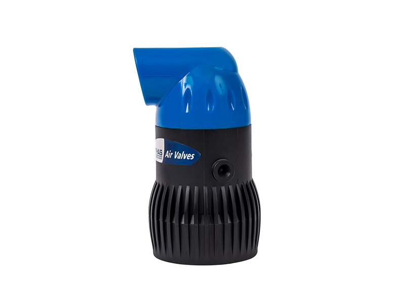
The broad categorization of these devices encompasses several distinct mechanical designs. Procuring the correct equipment requires matching the specific orifice mechanics to the operational demands of your fluid network. Selecting the wrong type will leave your infrastructure highly vulnerable.
| Valve Type | Orifice Design | Primary Function | Best Application Scenario |
|---|---|---|---|
| Air Vacuum Valve | Large Orifice | High-volume air exhaust during filling and intake during draining. | Mainline startup and shutdown protection against catastrophic vacuum collapse. |
| Air Release Valve | Small Orifice | Continuous venting of micro-bubbles under full system pressure. | High elevation points where entrained air creates flow bottlenecks. |
| Kinetic Air Valve | Dual Orifice | Combines high-volume transfer and continuous pressurized venting. | Complex networks requiring total fail-safe security and efficiency. |
The standard air vacuum valve is characterized by a large orifice designed specifically to handle massive volumes of air transfer. Its primary function is strictly limited to the startup and shutdown phases of a pipeline. It exhausts large quantities of air quickly as the pipe fills and admits large quantities of air instantly when the pipe drains. Importantly, once the system is fully pressurized and the float seals the large orifice, this specific valve will not open again until the internal pressure drops to near atmospheric levels. It cannot vent small air pockets that accumulate during active, pressurized operation.
Specifically designed for active systems, an air release valve features a very small internal orifice. Even after a system is fully filled and pressurized, small amounts of entrained air naturally separate from the fluid and gather at high elevations. If left unchecked, this accumulating air restricts fluid flow, creating artificial bottlenecks that drastically increase pump energy consumption. The small orifice design utilizes an internal leverage mechanism that allows the float to open against high internal pressure, continuously venting these micro-bubbles without releasing any fluid.
For comprehensive, fail-safe system security, engineers frequently specify a kinetic air valve. This advanced device integrates the functions of both the large orifice and small orifice designs into a single, compact unit. During startup, the large orifice exhausts high-velocity air. Once pressurized, the large orifice seals, but a secondary small orifice mechanism takes over to continuously vent accumulating air pockets. During shutdown, the large orifice instantly reopens to break the vacuum. This dual-functionality makes it the most robust option for complex piping networks.
The deployment of these pressure-regulating devices spans multiple sectors. While the underlying physics of fluid transport remain consistent, the specific application dictates the valve construction material and design specifications.
Modern agriculture relies on extensive, undulating networks of thin-walled PVC pipes, drip lines, and sprinkler matrices. Because farmland terrain is rarely perfectly flat, these systems are highly prone to air entrapment and vacuum formation during daily irrigation cycles. In this context, a dedicated irrigation air valve is a critical component.
For instance, deploying a 2-inch vacuum break valve engineered specifically for irrigation systems ensures high-capacity exhaust during startup. Top-tier agricultural models utilize UV-resistant engineering plastics and feature a dynamic low-pressure sealing mechanism. This guarantees the float seals completely even when system pressure drops to minimal operational levels, preventing unwanted leakage. When the main pump shuts off, the water drains rapidly to the lowest elevation. Strategically placed valves ensure the system drains cleanly without drawing in external mud or sand, saving crop yields and preventing underground pipe collapses.
Municipal infrastructure involves transporting millions of gallons of water over vast distances. Long-distance water transmission mains are particularly vulnerable to water hammer. A sudden pump failure at a municipal plant can send a devastating shockwave miles down the line, potentially bursting aging cast-iron pipes beneath city streets. In wastewater applications, specialized valves with elongated bodies are utilized. The elongated design keeps the mechanical sealing components far above the effluent, preventing raw sewage and solid waste from fouling the float mechanism.
Chemical processing plants and bulk liquid storage facilities face unique vacuum risks. Industrial storage tanks are often subjected to rapid emptying procedures or sudden temperature drops, which cause internal vapors to condense and shrink in volume rapidly. If a large steel storage tank is drained faster than air can enter, the external atmospheric pressure will easily overpower the structural integrity of the steel. These harsh environments require heavy-duty valves constructed from highly durable, corrosion-resistant materials.
Purchasing the correct valve is an engineering decision based on empirical data rather than estimation. An incorrectly sized valve provides a false sense of security and will inevitably fail to protect the system during a critical pressure event.
The most critical factor in selection is sizing the orifice to match the maximum potential airflow requirement of your system. Engineers must evaluate the filling rate, which is the maximum rate at which the pump introduces fluid into the empty pipe. The valve must exhaust air at this exact volumetric rate without blowing shut prematurely. Next, evaluate the drainage rate. This is the maximum rate at which fluid can exit the pipe, often calculated based on a worst-case scenario like a pipe burst at the lowest elevation. Using specialized nomographs provided by manufacturers, buyers must match the inlet diameter to the pipeline diameter and flow velocity.
The construction material must be chemically and environmentally compatible with both the internal fluid and the external installation site. Using the wrong material is a costly mistake.
Every valve features specific pressure ratings that must align with your operational parameters. Buyers must verify the Maximum Working Pressure to ensure the body will not rupture under peak system loads. Equally important is the minimum sealing pressure. Many valves require a minimum amount of internal fluid pressure, usually around 1.5 to 3 PSI, to push the float firmly against the upper elastomeric seal. If the system operates below this minimum threshold, the valve will continuously leak fluid because the float lacks the kinetic force to create a watertight closure.
Even the most accurately sized valve is rendered useless if installed in the wrong location or orientation. Strategic placement is dictated by the principles of fluid dynamics and topography.
Air naturally rises to the highest available point in a fluid system. Therefore, valves must be installed at specific topological and mechanical junctions. Critical installation points include the absolute high points of any hills along the pipeline route, and locations where a steep upward slope transitions to a flat run. Additionally, they should be placed immediately downstream of deep-well pumps to exhaust air introduced during startup, and upstream of check valves to prevent high-velocity air from damaging sensitive mechanical components.
These mechanisms rely entirely on gravity and vertical fluid buoyancy to operate. Consequently, they must be installed perfectly vertical. If a valve is installed horizontally or at a severe tilt, the internal float will scrape against the chamber walls. This friction prevents the float from rising to seal the orifice or dropping to admit air, rendering the device completely inoperable.
Standard engineering practice dictates installing a manual isolation valve, such as a ball valve or gate valve, directly beneath the unit. This simple addition allows maintenance personnel to isolate the device from the pressurized pipeline. If the unit requires cleaning, repair, or replacement, the operator can close the isolation valve without needing to shut down and drain the entire fluid network.
Like all mechanical devices, these valves require periodic observation to ensure ongoing reliability. When issues arise in the field, they usually manifest in one of two ways, both of which can be resolved through systematic troubleshooting.
If fluid is constantly weeping or spraying from the top orifice while the system is pressurized, the float is failing to create a proper seal. This is rarely a manufacturing defect. It is almost always an operational blockage. The most common culprit is debris, such as pipe scale, dirt, or stray Teflon tape from installation, trapped between the float and the rubber sealing ring. Alternatively, over years of use, the O-rings can degrade or lose elasticity, requiring a simple replacement. Finally, verify that the system is meeting the minimum pressure required to lift the float completely.
If the pipeline is experiencing violent surges or water hammer despite having a valve installed, the mechanism is likely failing to exhaust air. Start by checking for physical blockages. The external orifice may be obstructed by insect nests, mud, or frost. Another common issue is premature closure, also known as blow-up. If the valve is undersized, the aerodynamic force of the escaping air can suck the float upward, slamming it shut before the water even arrives, thereby trapping the remaining air inside.
To maximize the lifecycle of the equipment, facility managers should implement a strict bi-annual maintenance schedule. This routine involves closing the isolation valve, removing the top cover, and washing the internal float chamber to remove mineral scale or sediment. Inspecting the kinetic floats for structural integrity and checking the rubber seals for signs of wear will ensure the valve reacts instantly during sudden pressure events.
Managing air intake and exhaust is not merely an optional accessory. It is a fundamental requirement for safe, efficient fluid management. By automatically balancing internal and external pressures, these devices actively prevent costly vacuum collapses and mitigate destructive kinetic surges that can tear a system apart.
Are you ready to safeguard your fluid network? Evaluate your specific flow rates, topographical layout, and pressure ratings, then select the precise mechanical safeguard your project demands. Taking the time to properly size and install these mechanical safeguards today will save your facility from catastrophic failures and expensive downtime tomorrow. For high-performance, durable solutions tailored to your infrastructure, explore the complete range of professional air valves at ARKA Irrigation to find the exact match for your operational needs.
The primary distinction lies in their orifice size and operational timing. An air release valve utilizes a small orifice to continuously vent localized pockets of trapped air while the system remains fully pressurized and operational. In contrast, an air vacuum valve features a large orifice designed to move massive volumes of air in and out only during system filling and complete drainage. It does not vent air under normal pressurized conditions.
Generally, this is highly discouraged. Valves designed for agricultural irrigation are typically manufactured from high-grade plastics or nylon. While these materials handle water and dilute liquid fertilizers perfectly, they will degrade, warp, or melt rapidly when exposed to harsh industrial chemicals or extreme temperatures. Industrial pipelines require valves constructed from specialized, corrosion-resistant materials such as stainless steel, ductile iron, or Teflon.
Storage tanks and boilers are highly susceptible to severe pressure differentials caused by temperature and volume changes. When a boiler cools down, or when a bulk storage tank is rapidly drained, the internal volume of the fluid and vapor decreases. This creates a vacuum. Without a functional relief valve to admit atmospheric air and equalize the pressure, the immense weight of the external atmospheric pressure can physically crush or implode the steel structure.
Surge risks present clear physical indicators. The most obvious sign is a loud banging or hammering noise echoing through the pipes immediately after a pump activates or a valve closes. Additional indicators include sudden, violent pipe vibrations, recurring leaks at pipe joints, and the premature failure of downstream fittings and pump seals. If these symptoms are present, the system requires immediate pressure mitigation analysis.
Sizing depends on your pipeline diameter and the maximum flow rate of your water pump. As a general engineering rule of thumb, the valve inlet diameter should be roughly 1 inch for every 1000 gallons per minute of flow, but you must always consult the manufacturer flow charts. You need to ensure the valve can exhaust air at the exact rate the pump fills the pipe without blowing the internal float shut prematurely.
For agricultural and industrial applications, a bi-annual inspection is highly recommended. You should isolate the valve, remove the cap, and clean out any debris, scale, or insect nests that may block the orifice. Regularly checking the rubber seals for wear and tear ensures the valve will respond instantly when a critical pressure event occurs.


