
Views: 0 Author: Site Editor Publish Time: 2026-10-29 Origin: Site


Unexplained pipeline bursts and sudden flow drops are a costly nightmare for facility managers and agricultural operators alike. While water is the primary focus of any fluid network, it is rarely the only substance moving through the pipes. Invisible, highly compressible, and incredibly destructive, air is always present. Left unchecked, it easily becomes a pipeline network's worst enemy.
Unmanaged air creates artificial bottlenecks. These hidden blockages restrict flow and cause severe pressure spikes. Conversely, when water drains rapidly, the resulting negative pressure creates a powerful vacuum. I have seen this vacuum force crush heavy-duty pipes inward in mere seconds. To combat this dual threat, field engineers rely on one specialized device. That device is the combination air valve. In this comprehensive guide, we will break down exactly how this crucial equipment works. We will explore its internal mechanics and outline why proper installation is absolutely essential for everything from municipal water mains to agricultural irrigation networks.
Before examining the internal mechanics of air management devices, we need to understand exactly why air is present in closed fluid systems. Water and air possess entirely different fluid properties. When forced to share the same enclosed space, system efficiency degrades rapidly. This leads to massive spikes in operational costs.
Air enters pipelines through multiple standard operational avenues. High-capacity pumps introduce air through vortexes at the intake. Turbulent water absorbs atmospheric air at drop structures. Quite simply, pipelines are naturally full of air before they are filled with fluid. According to Henry's Law, water also contains dissolved air. This dissolved air separates into micro-bubbles whenever system pressure drops or temperature increases.
Because air is significantly lighter than water, these bubbles migrate to the highest elevations of the pipeline. Over time, they coalesce into large highly pressurized air pockets. The consequences of these trapped air pockets are measurable and severe. An air pocket acts as a physical restriction. It reduces the cross-sectional area of the pipe, creating a bottleneck that limits the volume of water passing through. Consequently, pumps must work significantly harder to push the same volume of water past the restriction. Furthermore, if an air pocket is suddenly dislodged and moves rapidly down the line, it can compress and expand violently. This creates pressure transients commonly known as water hammer. These shockwaves can easily exceed the pressure rating of the pipe and cause catastrophic bursts. To mitigate this, integrating a reliable air release valve is a non-negotiable engineering standard to bleed off this pressurized accumulation.
While positive pressure threatens to burst pipes outward, negative pressure threatens to crush them inward. Vacuum conditions typically form during rapid system draining, unexpected pump failures, or sudden valve closures. Imagine a municipal water main operating at peak hours. If a power outage trips the main pumps, the column of water continues to move down a slope due to gravity, leaving a massive void behind it.
If atmospheric air cannot enter the pipeline to fill this void, the internal pressure drops below the external atmospheric pressure. Many modern pipeline materials are engineered to withstand high internal pressure but possess very little resistance to external buckling forces. A vacuum can flatten a thin-walled steel or HDPE pipe instantly. Beyond structural collapse, negative pressure can suck contaminated groundwater or agricultural chemicals into the pipeline through microscopic gaps in pipe joints. This poses a massive threat to water security.
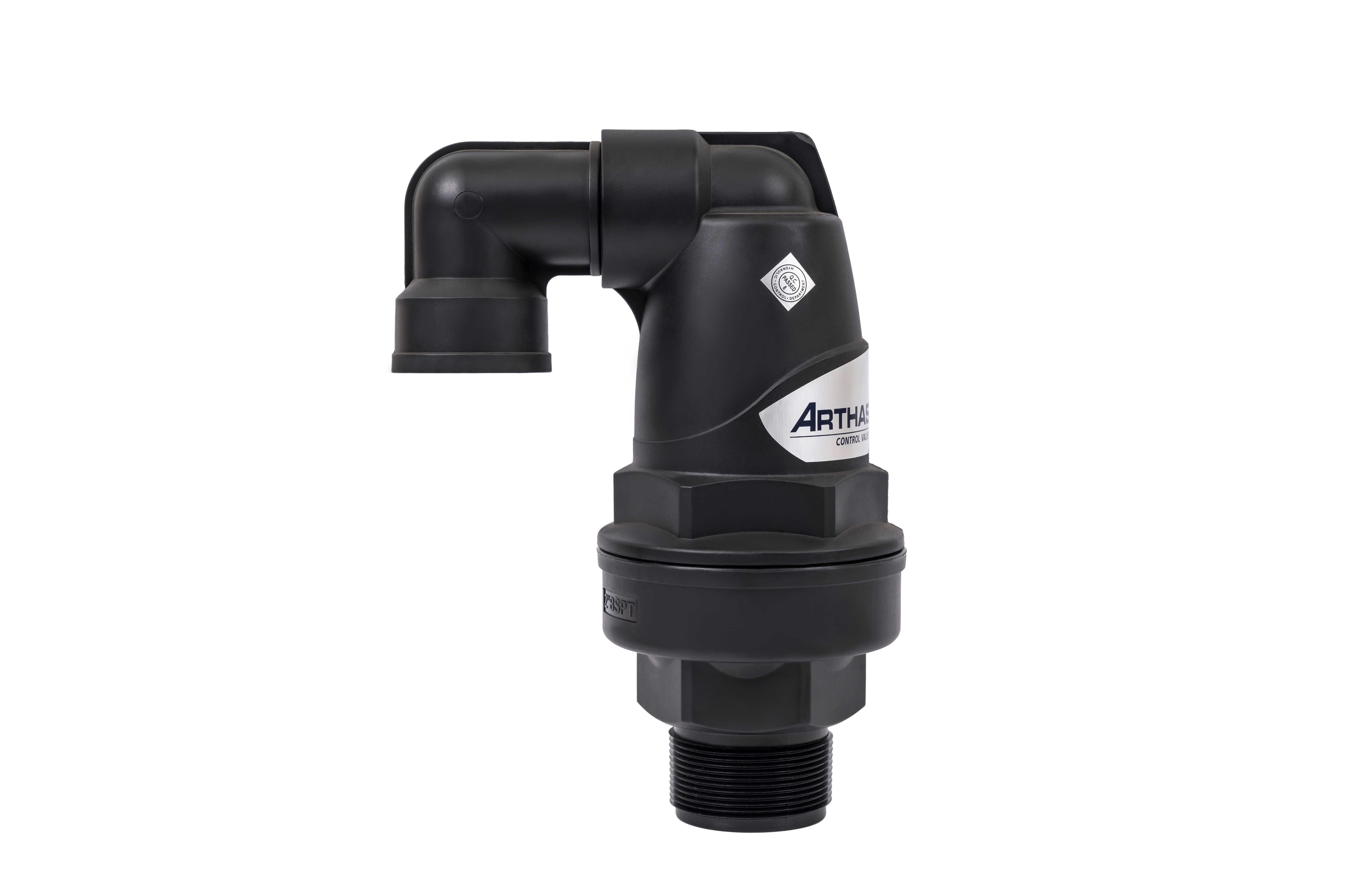
A combination air valve is frequently referred to in engineering specifications as a double orifice air valve. It is a highly specialized piece of equipment designed to mitigate both pressure blowouts and vacuum collapses simultaneously. Structurally, it houses two distinct orifices within a single valve body. It features a small orifice designed for releasing pressurized air and a large orifice designed for high-volume air intake and discharge.
By merging these two functions, engineers save significant space in underground vaults and reduce installation costs compared to piping separate single-function valves side-by-side. In addition, recent industry trend analyses highlight a growing shift in fluid management infrastructure toward climate-resilient designs. We are seeing a massive transition away from traditional heavy cast iron. Modern combination valves are increasingly manufactured from advanced UV-stabilized composite materials like reinforced nylon. This evolution prevents internal corrosion and scaling. It also significantly extends the operational lifespan of the network, reflecting a broader industry push toward sustainable and low-maintenance water management.
To truly understand the efficacy of this device, it is helpful to break down its autonomous operation into three distinct hydraulic phases. The internal floats respond directly to fluid level and pressure changes within the pipe. They require no external power source.
When a pump is initially activated, the empty pipeline is full of atmospheric air. As the water column rushes forward, it pushes this massive volume of air ahead of it at high velocity. During this phase, the heavy main float inside the combination valve rests at the bottom of the housing. This leaves the large orifice completely open.
Here, the device acts entirely as a kinetic air valve, venting rushing air into the atmosphere safely. Advanced aerodynamic designs within the chamber ensure that the high-velocity air does not blow the float upward prematurely. This prevents a dangerous phenomenon known as dynamic closure. For instance, high-quality units designed with a 2-inch interface are specifically engineered to handle massive exhaust volumes without slamming shut. The large orifice remains wide open until the water finally reaches the valve chamber, lifting the main float and sealing the large orifice tightly against the internal pressure.
Once the system is fully pressurized and water is flowing normally, the large orifice remains securely sealed. However, dissolved air continuously separates from the water, forming micro-bubbles that rise into the valve body. As this pressurized air accumulates at the top of the valve chamber, it slowly displaces the water.
The water level inside the valve drops slightly. This causes a secondary smaller float or a precision lever mechanism attached to the main float to lower. This precise mechanical movement opens a tiny orifice. The pressurized air bleeds out into the atmosphere with a distinct hiss without allowing any water to escape. Once the air is vented, the water level rises again. The small orifice immediately seals, maintaining perfect system equilibrium.
The final phase occurs when the pumps are turned off or a pipeline is intentionally drained for maintenance. As the water rapidly leaves the elevated section of the pipe, a dangerous vacuum begins to form. The moment the water pressure drops and the fluid level recedes from the valve chamber, the heavy main float loses its buoyancy and drops instantly.
This action opens the large orifice to its maximum capacity. Functioning now as an air vacuum valve, it draws massive amounts of atmospheric air directly into the pipeline. This incoming air breaks the vacuum, equalizing the internal and external pressure. It completely prevents the pipe from buckling, flattening, or collapsing inward.
When designing a fluid management system, procurement managers and engineers often confuse different types of protective valves. Understanding the specific mechanical distinctions is crucial for proper system design and avoiding catastrophic failures.
A standard air release unit is a single-function device. It features only a small orifice and a small float. Its sole purpose is to vent small amounts of accumulated air while the system is under working pressure. It lacks a large orifice entirely. Therefore, it cannot expel large volumes of air during pump start-up, nor can it draw in air to prevent a vacuum during shut-down. It is a partial solution at best.
A common misconception is that air valves and safety valves perform the same function. They absolutely do not. A safety valve or pressure relief valve is designed to manage water pressure. If the hydraulic pressure exceeds a predetermined safe limit, a spring-loaded mechanism opens to discharge water, preventing the pipe from bursting. In contrast, a comprehensive pipeline protection valve like a combination unit manages air volume. It operates based on fluid levels and buoyancy, not hydraulic pressure spikes. While both are critical for pipeline integrity, they perform entirely different jobs. They are frequently installed in tandem within complex fluid networks.
| Valve Type | Primary Function | High-Volume Exhaust | Vacuum Prevention |
|---|---|---|---|
| Combination Air Valve | Manages both micro-air release and large volume intake/exhaust. | Yes | Yes |
| Standard Air Release | Vents small pressurized air bubbles during normal operation. | No | No |
| Kinetic Valve | Exhausts and admits large air volumes at zero pressure. | Yes | Yes |
| Pressure Relief | Discharges water to prevent hydraulic over-pressurization. | No | No |
Even the highest quality valve will fail to protect a system if it is installed in the wrong location. The physics of air and water dictate precise non-negotiable installation points.
Because air is less dense than water, it naturally travels to the highest available elevation. Therefore, combination valves must be installed at absolute topographical high points along the pipeline route. Additionally, they should be placed at significant changes in the pipe gradient. This includes areas where a steep upward slope transitions to a flat or downward slope. Regular intervals along long horizontal runs are also required to prevent air from stagnating and binding the flow.
In municipal and industrial applications, these valves are often installed in underground dry vaults or protective boxes to prevent freezing and vandalism. When field technicians descend into a dry vault, they must ensure proper ventilation is in place. If the vault is completely sealed, the valve will not have access to atmospheric air to draw into the pipe during a vacuum event. This renders the device useless. Furthermore, security and cross-connection control are paramount. Utilizing one-way check valves on the air intake or routing vent pipes above the historical flood line are standard engineering practices to maintain pristine system security.
Agricultural fluid networks face unique hydraulic challenges that differ drastically from municipal water mains. Irrigation systems undergo frequent on and off cycles. They are often laid across highly undulating terrain and utilize thin-walled drip tapes or polyethylene tubing that are highly susceptible to deformation.
When an irrigation pump shuts off, the water drains rapidly to the lowest points of the field. Without proper air intake at the high points, a vacuum forms instantly. In a drip irrigation system, this vacuum causes the thin drip tapes to flatten out. Worse, the negative pressure creates a harsh suction effect at the emitters. This draws wet mud, dirt, and debris directly into the drip lines. Once dirt enters the microscopic labyrinth of an emitter, the system becomes permanently clogged. This leads to severe crop failure and expensive replacement costs.
Installing a dedicated irrigation air valve at the manifolds and sub-main high points ensures that air enters the system immediately upon shut-down. This keeps the drip tapes perfectly round and prevents mud suction. For outdoor agricultural use, choosing high-quality UV-resistant polymer valves is crucial to withstand harsh environmental conditions, intense sunlight, and corrosive agricultural chemicals.
Selecting the correct valve requires analyzing several specific system parameters. This ensures optimal hydraulic performance and prevents premature wear.
First, sizing is critical. The large orifice must be accurately sized based on the pipe's diameter, the pump's flow rate, and the pipeline's draining speed. For example, a robust C20 model featuring a 2-inch interface provides exceptional large exhaust volume capabilities for mainlines. An undersized valve will not intake air fast enough to prevent a vacuum. Conversely, an oversized valve can cause premature closure or unnecessary capital expenditure.
Second, material selection depends heavily on the fluid and environment. While ductile iron is standard for municipal water, systems handling corrosive fluids or requiring lightweight field installations benefit greatly from specialized composite plastics. Finally, verify the working pressure. The valve must be rated for the system's maximum operating pressure to prevent body rupture, while also being sensitive enough to seal properly at the system's lowest operational pressure.
Managing the air inside a pipeline is just as critical as managing the fluid itself. Uncontrolled air accumulation leads to restricted flow, inaccurate metering, and wasted energy. Meanwhile, vacuum conditions threaten the structural integrity of the entire network.
A combination air valve stands as the most cost-effective and comprehensive solution available today. By seamlessly integrating kinetic air discharge, pressurized air release, and high-capacity vacuum protection into a single unit, it offers unparalleled peace of mind. Facility managers, irrigation specialists, and engineers should regularly evaluate their current pipeline designs and upgrade their air management systems to ensure maximum efficiency.
Ready to safeguard your fluid network? Explore high-quality air management solutions and find the exact specifications for your project at ARKA Irrigation.
Failing to install proper air management devices leads to severe operational and structural issues. Trapped air creates artificial bottlenecks, restricting water flow and forcing pumps to consume significantly more electrical energy to maintain pressure. Furthermore, without vacuum protection during drainage or pump failures, negative pressure can easily exceed the structural integrity of the pipe. This leads to catastrophic inward collapse, especially in thin-walled plastics or large-diameter steel pipes.
Yes, it acts as a highly effective indirect mitigation tool for water hammer. Water hammer is often exacerbated by trapped air pockets. Because air is highly compressible, a sudden change in fluid velocity causes these air pockets to compress and expand violently. This sends destructive shockwaves through the piping network. By continuously bleeding out pressurized air and ensuring the pipe remains completely filled with incompressible water, the valve stabilizes fluid dynamics and significantly reduces the severity of transient pressure surges.
No, they serve different operational scopes. A kinetic valve only operates when the system is at zero or near-zero pressure, exhausting large volumes of air during pipe filling and admitting atmospheric air during drainage. However, once the pipe is fully pressurized, the kinetic float seals shut and cannot open again to release the small air bubbles that accumulate during normal operation. A combination valve integrates this kinetic function with an automatic micro-release mechanism, providing comprehensive protection across all operational phases.
Sizing depends on the pipeline diameter, the maximum flow rate during filling, and the drainage rate during shut-off. A general engineering rule of thumb is to size the air valve at approximately 1 inch of valve diameter for every 1 foot of pipe diameter, though this varies by manufacturer flow charts. Utilizing models with a large exhaust volume, such as those with a 2-inch interface, ensures sufficient airflow to protect sub-mains and manifolds from vacuum collapse.
They must be installed at absolute topographical high points of the pipeline system. They are also required at changes in downward slope, downstream of pumps, upstream of check valves, and at regular intervals of roughly 1,500 to 2,500 feet along long horizontal pipe runs to prevent localized air accumulation.


