
Views: 0 Author: Site Editor Publish Time: 2026-07-31 Origin: Site


Negative pressure in commercial and agricultural drip irrigation systems creates hidden, compounding damage that destroys infrastructure from the inside out. When a pump shuts down or a zone valve closes, water rapidly drains from the lower elevations of the piping network. This sudden evacuation creates a powerful vacuum at higher elevations. Without proper air management, this vacuum triggers "suck-back," a destructive physical process where soil, debris, and pathogens are pulled directly into the micro-emitters.
The impact is especially catastrophic for Sub-surface Drip Irrigation (SDI) systems. Because these emitters are buried directly in the soil matrix, a vacuum event guarantees immediate ingestion of mud and grit, leading to irreversible clogging and lateral line collapse. You cannot simply flush this damage away. To protect emitter integrity and preserve your capital investment, installing a vacuum break valve is a non-negotiable infrastructure requirement. These devices neutralize negative pressure immediately upon system shutdown.
System Integrity: Vacuum break valves prevent soil ingestion and emitter clogging by immediately introducing air into the pipeline when negative pressure is detected.
Component Differentiation: While often confused, a dedicated vacuum break valve serves a different primary function than a standard irrigation air release valve, though combination kinetic air valves can perform both tasks.
Strategic Placement: Effective protection requires precise valve placement at system high points, manifold transitions, and the ends of lateral lines, dictated by the specific topography and depth of the installation.
ROI and Risk Mitigation: The minimal upfront cost of an irrigation pipeline valve is vastly outweighed by the reduction in labor for flushing lines, replacing clogged emitters, and repairing collapsed thin-wall drip tape.
A successful, pressure-balanced irrigation cycle requires smooth transitions. During startup, air must exit the lines seamlessly to prevent pressure surges. During operation, water must flow uniformly at the designed pressure threshold. Finally, during shutdown, the system must depressurize without creating a vacuum. When all three phases occur correctly, emitters deliver exact flow rates, and the piping remains structurally sound.
Vacuum formation disrupts this balance entirely. As the irrigation cycle ends, gravity forces water down sloped terrain. The water exiting the lowest emitters acts like a piston pulling downward in a cylinder. Sudden pump shutdowns, power failures, or rapid valve closures accelerate this drainage. The faster the water leaves the system, the stronger the vacuum created at the top of the slope.
This negative pressure results in the costly phenomenon known as suck-back. When a vacuum forms, the system desperately seeks to equalize pressure by pulling air through any available opening. In a drip system, those openings are the micro-emitters. As air rushes in, it drags surrounding wet soil, sand, and debris directly into the emitter labyrinth. This physical ingestion instantly clogs the precision pathways designed to regulate water flow.
Beyond physical clogging, suck-back introduces severe biological risks. Pathogens, bacteria, and organic matter enter the warm, nutrient-rich environment of the drip line. This triggers rapid biofilm buildup and root intrusion, further choking the system. Additionally, thin-wall drip tape lacks the structural rigidity to withstand strong negative pressure. Under vacuum conditions, the tape physically flattens and collapses, causing permanent creases that disrupt future water flow and weaken the plastic.
Sub-surface Drip Irrigation (SDI) faces the highest vulnerability. Underground systems carry a 10x higher risk of immediate, irreversible emitter failure due to negative pressure. Because the emitters are entirely encased in backfill soil, any vacuum directly sucks mud into the orifice. Unlike surface systems that might only pull in clean air, SDI systems ingest dense particulates that permanently destroy the emitter's functionality.
Flattened or creased drip tape sections visible upon excavation.
Mud and fine silt found inside the emitter labyrinth during autopsy.
Uneven crop growth patterns specifically at higher elevations.
Sudden spikes in system operating pressure indicating widespread clogging.
Selecting the right air management equipment requires categorizing valves by their specific functions. Misunderstanding these categories leads to unprotected zones and rapid system failure. You must match the valve type to the specific pneumatic demands of your irrigation network.
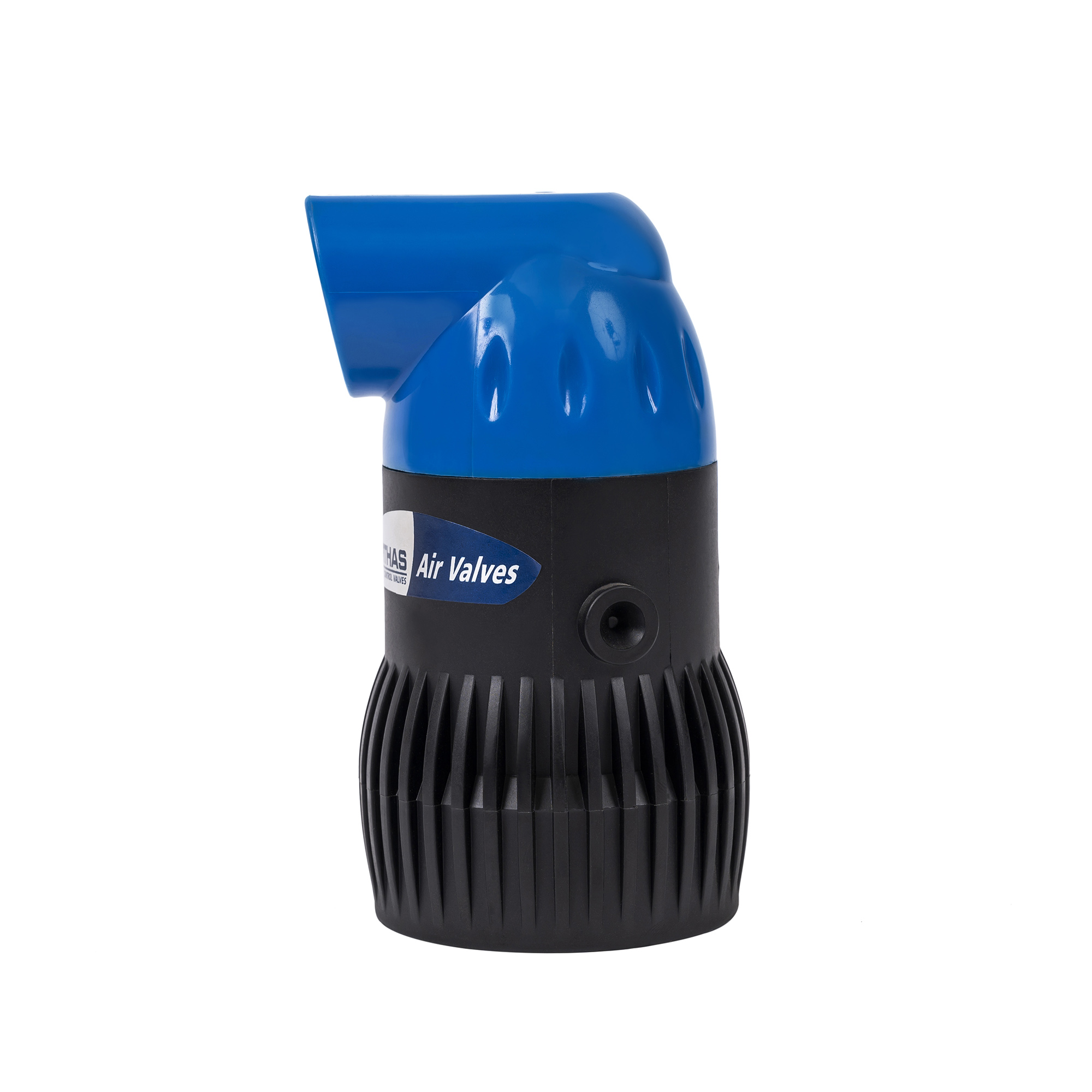
The dedicated vacuum break valve serves a single function. It features a large orifice designed to open rapidly at near-zero or negative pressure. When the system shuts down and water drains, this valve drops open to admit massive volumes of atmospheric air. By filling the void left by draining water, it instantly equalizes pipeline pressure and entirely prevents vacuum formation.
Contrast vacuum relief with air release. An irrigation air release valve performs the opposite function. It expels trapped air pockets while the system is actively pressurizing. This prevents localized pressure spikes and water hammer. A standard air release valve will not protect against suck-back because its orifice is too small to admit the large volumes of air required during rapid drainage.
For comprehensive protection, many operators utilize a kinetic air valve. This combination device merges both functions into a single unit. It provides high-volume air discharge during system startup and high-volume air intake during shutdown. A combination valve is highly preferable in undulating topographies or large-scale agricultural setups where both trapped air and vacuum formation pose significant threats to the infrastructure.
Choosing the correct valve specifications dictates the success of your air management strategy. You must evaluate sizing, material durability, and sealing thresholds to ensure reliable field performance.
Sizing and orifice capacity determine how effectively the valve neutralizes negative pressure. You calculate the required air intake volume based on the maximum water drainage flow rate, the slope gradient, and the pipe diameter. The valve must admit air at a rate equal to or greater than the rate of water draining away.
Undersizing restricts air intake, allowing a partial vacuum to form. This leads to partial tape collapse and minor suck-back events that accumulate over time. Oversizing introduces unnecessary costs, creates physical space constraints in valve boxes, and can cause sealing issues if the system lacks the pressure to lift a massive float.
Material durability dictates the lifespan of the valve in harsh environments. Polymer and glass-reinforced nylon constructions offer excellent resistance to corrosion and UV degradation, making them ideal for most agricultural applications. Brass and metal constructions provide superior resistance to physical impacts and extreme pressure surges but are susceptible to chemical corrosion. You must assess chemical resistance carefully, especially if your operation relies on fertigation, chlorination, or acid injection systems. The internal seals and floats must withstand these aggressive chemicals without degrading.
Sealing pressure thresholds define when the valve closes. You must analyze the minimum operating pressure required for the internal float to seal completely against the orifice. If your system operates at very low pressures, a valve with a high sealing threshold will continuously weep water during the irrigation cycle. Always verify manufacturer sealing specifications against your zone's lowest operating pressure.
Valve Type | Primary Function | Best Application | Limitation |
|---|---|---|---|
Dedicated Vacuum Breaker | Admits high-volume air during shutdown | Flat terrain, end of lateral lines | Cannot expel trapped air under pressure |
Continuous Air Release | Expels small air pockets under pressure | High points on pressurized mains | Cannot prevent vacuum during rapid drainage |
Kinetic Air Valve | High-volume air intake and discharge | Undulating terrain, complex manifolds | Requires careful sizing to prevent water hammer |
Scaling valve deployment across complex agricultural or commercial topographies requires precise placement. Random installation leaves critical zones unprotected. You must map the elevation changes across your entire irrigation network.
Placing valves at high points is an absolute necessity. Any elevation change exceeding a 2% grade requires vacuum relief at the apex. As water drains down both sides of a hill, the highest point experiences the most severe vacuum forces. Protecting these peaks ensures the entire downstream lateral remains pressure-balanced.
Manifolds and sub-mains represent critical transition points. These large-diameter pipes distribute massive volumes of water into the smaller lateral lines. Installing an irrigation pipeline valve at the head of these manifolds prevents a vacuum from pulling water backward out of the laterals when the zone valve closes.
The ends of lateral lines are equally vulnerable. Using flush valves with integrated vacuum relief at the furthest points of the drip system provides a final layer of defense. This ensures air can enter the system from both ends, rapidly equalizing pressure across long runs of drip tape.
Sub-surface specific configurations require extra planning. You cannot bury air valves directly in the dirt. Design guidelines mandate placing these valves in accessible, debris-protected valve boxes. The boxes must sit slightly above grade to prevent surface water from flooding the enclosure and being sucked into the valve during a vacuum event.
Evaluating the overall value of air management infrastructure requires comparing upfront capital expenditures against long-term operational costs. Installing high-quality kinetic air valves across all zones requires an initial investment. However, operating without them guarantees escalating maintenance expenses.
The labor savings alone justify the installation. Without vacuum relief, maintenance crews spend countless hours flushing mud out of lateral lines and applying harsh chemical treatments to dissolve clogs. By preventing suck-back, you eliminate this reactive maintenance. Your crews can focus on optimization rather than constant repair.
Furthermore, vacuum relief dramatically extends the lifespan of your drip tubing and tape. Preventing physical collapse and internal abrasion keeps the plastic structurally sound for years longer than unprotected systems. Framing these valves as an essential insurance policy clarifies their value. The cost of a single valve is negligible compared to the expense of trenching, removing, and replacing thousands of feet of ruined SDI tape.
Installing and maintaining these valves in the field presents specific challenges. Anticipating these risks ensures your air management strategy remains effective season after season.
Improper sizing often leads to water hammer. If a kinetic valve expels air too rapidly during startup, the sudden arrival of the water column slams the float shut, sending a destructive shockwave through the pipes. You mitigate this by utilizing valves with anti-slam mechanisms or multi-stage closures. These designs throttle the air discharge just before the water arrives, ensuring a soft, controlled closure.
Debris accumulation causes valve seating failure. Dirt, dust, or insect nests can prevent the internal float from sealing, causing constant water leakage. Establish a strict preventative maintenance schedule for inspecting and cleaning valve seats. Select valves with shielded, screened intakes to prevent mud daubers and spiders from nesting inside the orifice.
Chemical crystallization from fertigation degrades internal components. Fertilizers and acids can dry on the valve seals, creating hard crystals that prevent a watertight seal. Mitigate this by installing valves upstream of fertilizer injection points whenever possible. If downstream installation is unavoidable, select valves featuring self-cleaning internal mechanisms and chemical-resistant elastomer seals.
Winterization and freeze damage destroy unprotected valves. Water trapped inside the valve body will expand and crack the plastic during a hard freeze. Implement proper drainage protocols before winter. Evaluate frost-resistant valve designs, install protective insulation jackets, or ensure the valves feature threaded connections making them easily removable during off-season winterization.
Conduct a comprehensive topographical audit of your irrigation network to identify all high points and vulnerable slopes exceeding a 2% grade.
Calculate your specific air volume intake requirements based on the maximum water drainage rates of your manifolds and lateral lines.
Inspect existing valve boxes to ensure they are installed above grade and free of debris that could be ingested during a vacuum event.
Consult with an irrigation engineer to procure and install correctly sized kinetic air valves at all critical manifold transitions.
A: An air release valve slowly expels trapped air pockets while the system is pressurized. A vacuum break valve rapidly admits air into the system when pressure drops to prevent a vacuum from forming during shutdown.
A: Yes. A kinetic air valve is a combination device that performs both functions. It releases large volumes of air during system startup and admits large volumes of air during shutdown to break the vacuum.
A: The most critical locations are at the highest topographical points of the irrigation system, at the ends of the lateral lines, and at the head of sub-mains where vacuum forces are most likely to pull in soil.
A: By introducing air into the line during shutdown, it equalizes the pressure. This prevents the system from creating a suction effect that pulls wet soil, roots, and debris backward through the emitter orifices.
A: An undersized valve will not admit air fast enough to equalize pressure. This allows a partial vacuum to form, which can still result in soil suck-back or the physical flattening of thin-wall drip tape.
A: Low-quality or improperly specified valves may weep if the system's operating pressure does not reach the minimum threshold required to force the internal float to seal. Always check the manufacturer's minimum sealing pressure.


