
Views: 0 Author: Site Editor Publish Time: 2026-10-08 Origin: Site


Serving as the operational heart of modern industrial and agricultural water filtration, the automatic disc filter valve acts as the primary mechanical director. It manages the complex hydraulic pathways required to transition a filter from standard operation into a self-cleaning state. Without this critical component, the system remains entirely static. Facility managers are then forced into constant, labor-intensive human intervention just to maintain optimal flow rates and prevent pressure drops.
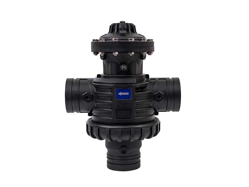
Engineers meticulously design the architecture of these specialized valves. They must deliver high-cycle durability. Precise fluid control is simply non-negotiable. The primary components include the robust valve body, typically constructed from glass-reinforced polyamides or heavy-duty cast iron. We choose these materials specifically to withstand high internal hydrostatic pressure. They also aggressively resist corrosion from agricultural fertilizers or harsh industrial chemical treatments. Inside the body, the internal diaphragm or piston acts as the moving barrier. Responding instantly to hydraulic pressure changes, it shifts position to open or close specific flow ports. Finally, the solenoid control bridges the electronic controller and the hydraulic valve. It converts low-voltage electrical signals into the physical movement that allows pressurized water to enter the control chamber.
Strategically positioned at the critical intersection of the raw water inlet, the filter housing, and the drainage manifold, the valve dictates the entire flow cycle. During standard operation, it permits raw water to seamlessly enter the disc filter system. However, when a cleaning cycle triggers, the internal geometry of the valve rapidly alters. It completely seals off the raw water inlet. Instantly, it opens a direct, unrestricted pathway to the atmospheric drain. This fundamentally changes the internal pressure dynamics within the housing.
To truly grasp the valve's function, one must first examine the mechanics of the filtration media itself. Disc filtration relies on a robust three-dimensional depth matrix. This provides a massive advantage over a simple two-dimensional surface screen.
The core of the setup consists of hundreds of synthetic, color-coded discs stacked tightly on a central, hollow spine. Each individual disc features microscopic, diagonally etched grooves. When compressed, the grooves of adjacent discs intersect. They create a highly complex, tortuous network of internal passageways. Mechanical spring tension, combined with the immense hydraulic pressure of the incoming fluid, tightly binds these discs together. Raw water is forced from the outer perimeter of the stack toward the inner spine. As the fluid navigates the intersecting grooves, suspended solids, sand, and sticky organic matter like algae become trapped deep within the matrix. Consequently, only highly purified water reaches the inner spine to be transported downstream.
As debris inevitably accumulates within these microscopic grooves, the pathway for water becomes severely restricted. This restriction causes a measurable, immediate drop in water pressure on the downstream side of the manifold. Automated setups utilize a highly sensitive Pressure Differential switch to continuously monitor this fluctuation. It compares raw inlet pressure against the filtered outlet pressure. When the difference reaches a pre-calibrated threshold—typically between 7 to 10 PSI, which is roughly 0.5 to 0.7 bar—the electronic controller registers that the media is sufficiently fouled. Once this specific trigger condition is met, the controller bypasses normal operation and initiates the backwash sequence.
The critical transition from active filtration to backwashing requires exact timing and precise hydraulic control. These specialized valves execute this complex, multi-stage sequence in a matter of milliseconds to prevent system shock.
The cycle begins the exact instant the controller identifies a critical pressure drop. The electronic controller sends a low-voltage electrical impulse directly to the solenoid. Energizing immediately, the solenoid opens a micro-port that allows pressurized water to flood the control chamber of the back-flushing control valve. This sudden influx of hydraulic pressure forces the internal elastomeric diaphragm to shift its position. It fundamentally alters the flow of water through the entire isolated pod.
As the diaphragm shifts, two critical hydraulic actions occur simultaneously. First, the pathway from the raw water source is completely sealed off for that specific filter pod. This isolates it from the main feed. Second, a large port connecting the filter housing directly to the atmospheric drain line is thrown open. Because the drain rests at atmospheric pressure, the internal pressure within the filter housing drops rapidly. This sudden decompression releases the hydraulic force that was keeping the discs compressed. The mechanical spring on the spine relaxes, allowing the individual plastic rings to separate slightly.
With the discs decompressed and loose, clean filtered water from adjacent operating filters is introduced into the hollow central spine of the isolated pod. This clean fluid is forced outward through specialized, angled nozzles located along the spine. Because the discs are no longer tightly bound, the high-velocity jets of water cause them to spin rapidly. This dynamic combination of centrifugal force and reverse inside-out water flow aggressively scours the plastic rings. It effectively dislodges the trapped organic debris and silt. The highly contaminated wastewater is then flushed out through the open drainage port.
Once the precisely programmed backwash duration concludes—usually lasting just 10 to 20 seconds—the controller de-energizes the solenoid. The control chamber quickly vents, allowing the diaphragm to return to its original seated position. The drain port firmly closes, the raw water inlet reopens, and hydraulic pressure immediately re-compresses the stack. The pod instantly returns to the active filtration phase.
| Phase | Valve Position | Disc State | Water Flow Direction | Action |
|---|---|---|---|---|
| Filtration | Inlet Open, Drain Closed | Compressed | Outside-In | Trapping debris in grooves |
| Transition | Diaphragm Shifting | Decompressing | Stopping | Preparing for cleaning cycle |
| Backwash | Inlet Closed, Drain Open | Loose & Spinning | Inside-Out | Flushing debris to atmospheric drain |
| Return | Inlet Open, Drain Closed | Re-compressing | Outside-In | Resuming normal filtration |
In large-scale commercial operations, shutting down the primary water supply to clean a filter is often an unacceptable compromise. It halts production and damages bottom lines. This operational hurdle is exactly where advanced manifold configurations prove their immense worth.
A dual backwash valve is a highly specialized configuration utilized heavily in multi-pod filter manifolds. Instead of relying on a single master valve to control the entire filtration plant, each individual filter housing is equipped with a dedicated valve. Top-tier models, like the F90FM series, offer high-quality plastic or metal bodies that independently manage both the inlet of raw water and the reverse flow of clean water.
The primary operational advantage of this localized setup is the absolute guarantee of continuous downstream flow. When the pressure switch triggers a cleaning cycle, the controller smartly isolates only one filter pod at a time. The active valve on the dirty pod shifts to the cleaning position. Meanwhile, the remaining filter pods in the manifold continue to operate normally. A small, calculated portion of the clean water produced by the active pods is diverted backward through the isolated pod. This facilitates the inside-out flushing process. Therefore, the downstream application never experiences a cessation of water supply. By utilizing the existing system pressure generated by the main water pump, the need for a secondary backwash pump is completely eliminated. This reduces capital expenditure and lowers overall energy consumption.
Recent market data reveals a massive global shift towards smart, IoT-enabled filtration infrastructures. Industrial plants and massive agricultural grids are abandoning static filters. Why? Water scarcity is driving up operational costs. Facilities can no longer afford to waste thousands of gallons on inefficient manual flushes. Today's trend heavily favors predictive maintenance. Systems now integrate automated hydraulic valves with cloud-based monitoring. Facility managers and agronomists demand real-time data on pressure differentials and backwash frequencies. They can catch fouling before a catastrophic pressure drop halts production. This evolution from reactive manual cleaning to predictive, automated maintenance is quickly becoming a baseline requirement for sustainable water management.
For engineering teams and facility managers, the decision to upgrade from manual screen filters to automated disc systems is largely driven by empirical data. It comes down to operational efficiency, risk mitigation, and long-term cost reduction.
Picture a maintenance crew trudging through a muddy agricultural field or a cramped industrial utility room to physically isolate a filter bank. They must manually bleed the pressure, wrench open the heavy housing, pull out the slime-coated filtration element, and aggressively scrub it down with acid or stiff brushes. This archaic process easily consumes an hour per filter. It also poses unnecessary safety risks to personnel. Implementing a backwash hydraulic valve automates this entirely. The system self-cleans in mere seconds without any human intervention. You can reallocate your maintenance personnel to more critical tasks and drastically slash operational expenditures.
Manual cleaning routines or poorly calibrated timer-based systems notoriously waste significant amounts of water. In stark contrast, automated valves triggered strictly by pressure differentials ensure that the system only flushes when it is empirically necessary based on actual dirt load. Furthermore, the high-velocity centrifugal spinning of the discs requires very little fluid to achieve a pristine clean. In properly sized systems, wastewater generation typically accounts for less than one percent of the total water volume processed. This makes it an incredibly green engineering solution.
When manual filters clog, the downstream pressure drops exponentially over time. This continuous fluctuation causes severe operational issues. You might see uneven water distribution across crop rows or inadequate flow to sensitive industrial cooling towers. Because these automated valves trigger a cleaning cycle at a very specific, low-level pressure drop, the downstream pressure remains highly consistent. This unwavering reliability effectively protects secondary equipment from cavitation, starvation, and premature wear.
The robust physical nature and intelligent self-cleaning capabilities of these automated setups make them perfectly suited for a variety of demanding environments. In these high-stakes applications, water quality cannot be compromised.
Selecting the correct components for your water filtration infrastructure is a critical engineering decision. The overall efficiency of an automated setup relies heavily on meticulously matching the technical specifications of the valves to the precise demands of your water source. Over-sizing wastes valuable capital. Under-sizing inevitably leads to continuous backwashing, excessive head loss, and premature system failure.
The most fundamental specification during procurement is the flow rate capacity, typically measured in gallons per minute or cubic meters per hour. System designers must accurately calculate both the peak flow rate of the entire manifold and the specific required flow rate for a single backwashing sequence. This ensures optimal fluid velocity. Products like the F90FM series are engineered to handle these dynamic shifts flawlessly.
| Valve Size | Typical Flow Rate Range | Recommended Application Scale |
|---|---|---|
| 2-Inch | 40 - 110 gallons per minute | Low-flow agricultural drip zones, small cooling towers. |
| 3-Inch | 100 - 250 gallons per minute | Mid-sized industrial pre-filtration, municipal intakes. |
| 4-Inch | 200 - 450 gallons per minute | Heavy industrial process water, large agricultural manifolds. |
The operational mechanics of these valves depend entirely on precise fluid dynamics. For the cleaning cycle to function correctly, the system must maintain a specific minimum pressure during the backwash phase. If the system pressure is too low, the discs will not separate adequately. The vital centrifugal spinning action will fail. Most industrial and agricultural systems require a minimum dynamic pressure of 30 to 40 PSI at the valve inlet. Facilities operating low-pressure systems may need to integrate a secondary booster pump. Alternatively, they can utilize specialized dual-valve configurations to artificially hold the pressure in the manifold during a flush.
The operating environment strongly dictates the required valve material. Engineered plastics, such as reinforced polyamides, are highly resistant to chemical corrosion. This makes them the standard choice for agricultural fertigation or brackish water desalination. Conversely, ductile iron or stainless steel components are absolutely necessary for extreme high-pressure industrial environments. Mining operations or municipal water mains, where dangerous pressure spikes and water hammers are common occurrences, demand metal bodies.
While an automated setup drastically reduces the grueling manual labor associated with water treatment, it is not entirely maintenance-free. Establishing a proactive, condition-based maintenance schedule is essential. It preserves hydraulic efficiency and prevents unexpected, costly downtime.
Facility managers should implement a structured inspection routine. Focus heavily on the components that actuate the backwash cycle. Routine checks should include inspecting the small hydraulic command tubes for pinhole leaks, kinks, or UV degradation. Additionally, technicians must manually trigger a backwash via the controller quarterly to ensure the solenoids click and energize properly. Bi-annually, the differential pressure switch should be carefully calibrated. Clean its sensor ports to ensure the system accurately detects pressure drops.
Even with rigorous maintenance, highly reliable systems can encounter operational faults. Understanding the mechanical relationship between the controller and the valves aids in rapid, effective troubleshooting.
Automatic disc filter valves have fundamentally transformed how modern industries approach water filtration. By eliminating the archaic need for manual scrubbing, these intelligent systems drastically reduce labor costs. Simultaneously, they protect sensitive downstream equipment from catastrophic clogging. Whether your facility relies on a standard configuration or a highly advanced manifold utilizing dual-valve technology, the transition to automated filtration is a sound financial investment. It ensures optimized water conservation, highly consistent hydraulic pressure, and long-term operational reliability that manual filters simply cannot match.
Ready to upgrade your filtration infrastructure? If you are designing a new water treatment manifold or upgrading a legacy system, precision matters. Do not let inferior valves bottleneck your operation. Explore the full range of high-performance filtration solutions, including the robust F90FM series, at Arka Irrigation. Their engineering team can help you match the exact valve specifications to your site's unique demands. Visit their official site today to secure reliable, continuous water flow for your next project.
A screen filter utilizes a two-dimensional stainless steel or plastic mesh to block debris, which is highly effective for hard, inorganic particles like sand. However, soft organic matter such as algae can easily deform and extrude through a simple screen under pressure. In contrast, a disc filter utilizes hundreds of stacked, grooved rings to create a complex three-dimensional depth matrix. This provides a significantly larger surface area and is vastly more effective at capturing soft, organic material from surface water sources.
To achieve an effective and thorough cleaning cycle, the valve requires sufficient hydraulic pressure to decompress the stacked discs and force water through them in reverse. Engineers typically recommend maintaining a minimum dynamic pressure of 30 to 40 PSI at the valve inlet during the backwash phase. If the pressure falls below this critical threshold, the discs will fail to spin fast enough to eject trapped debris, leading to rapid re-clogging and system failure.
Unlike older, inefficient timer-based setups, modern automated filtration should never backwash on a rigid, inflexible schedule. Instead, the frequency is entirely dictated by the Total Suspended Solids present in your specific water source. The system utilizes a differential pressure switch that constantly monitors the pressure difference across the manifold. The controller is programmed to trigger the cleaning cycle only when this differential reaches a specific threshold, ensuring the system uses flush water exactly when empirically necessary.
Technically, it is possible to retrofit a manual housing by removing the manual caps, installing hydraulic valves, building a custom drainage manifold, and wiring an external electronic controller. However, from an engineering and cost-efficiency perspective, this is rarely recommended. Manual filter housings are not always structurally designed to withstand the rapid, violent hydraulic shifts and reverse flow pressures associated with automated cleaning. Purchasing a purpose-built automated system ensures that the manifold geometry, valve sizing, and internal spines are perfectly calibrated for long-term reliability.
When properly sized and calibrated, automated disc filters are incredibly water-efficient. Because they rely on high-velocity centrifugal spinning rather than massive water volume to clean the discs, a single backwash cycle usually lasts only 10 to 20 seconds. In most well-designed industrial or agricultural manifolds, the total wastewater generated accounts for less than one percent of the total filtered water volume.
If you are experiencing downstream pressure drops despite having an automated system, the filter is likely failing to clean itself properly during the backwash cycle. This is most commonly caused by insufficient backwash pressure at the valve inlet, which prevents the discs from separating and spinning. It can also be caused by a clogged hydraulic command tube failing to actuate the valve fully, or a faulty differential pressure switch that is not triggering the flush cycle when the dirt load threshold is reached.


